ASSEMBLY/SETUP INSTRUCTIONS
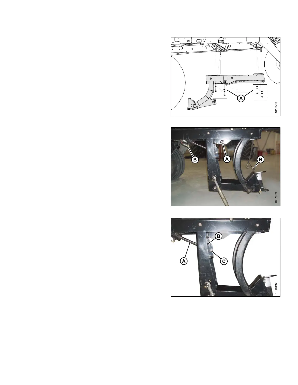
10. Attach the linkage with four flat washers, lock washers ,
and nuts (A).
Figure 2.43: Linkage Forward
11. Lower linkage by pulling on safety pin (A) on the
left-hand side of linkage.
12. If the linkage does not lower, remove plugs at the end
of lift cylinder hoses (B) to remove air from hoses.
Figure 2.44: DWA Linkage
13. Secure the lift cylinder pivot (A) into the correct hole
depending on header type:
• For R-Series header: insert pin in the upper hole (B)
• For D-Series or A-Series header: insert pin in the
lower hole (C)
Figure 2.45: Lift Cylinder Pivot
214049 29 Revision A
 Loading...


