ASSEMBLY/SETUP IN STRUC TIONS
2.7 Installing the Auxiliary Valve Block
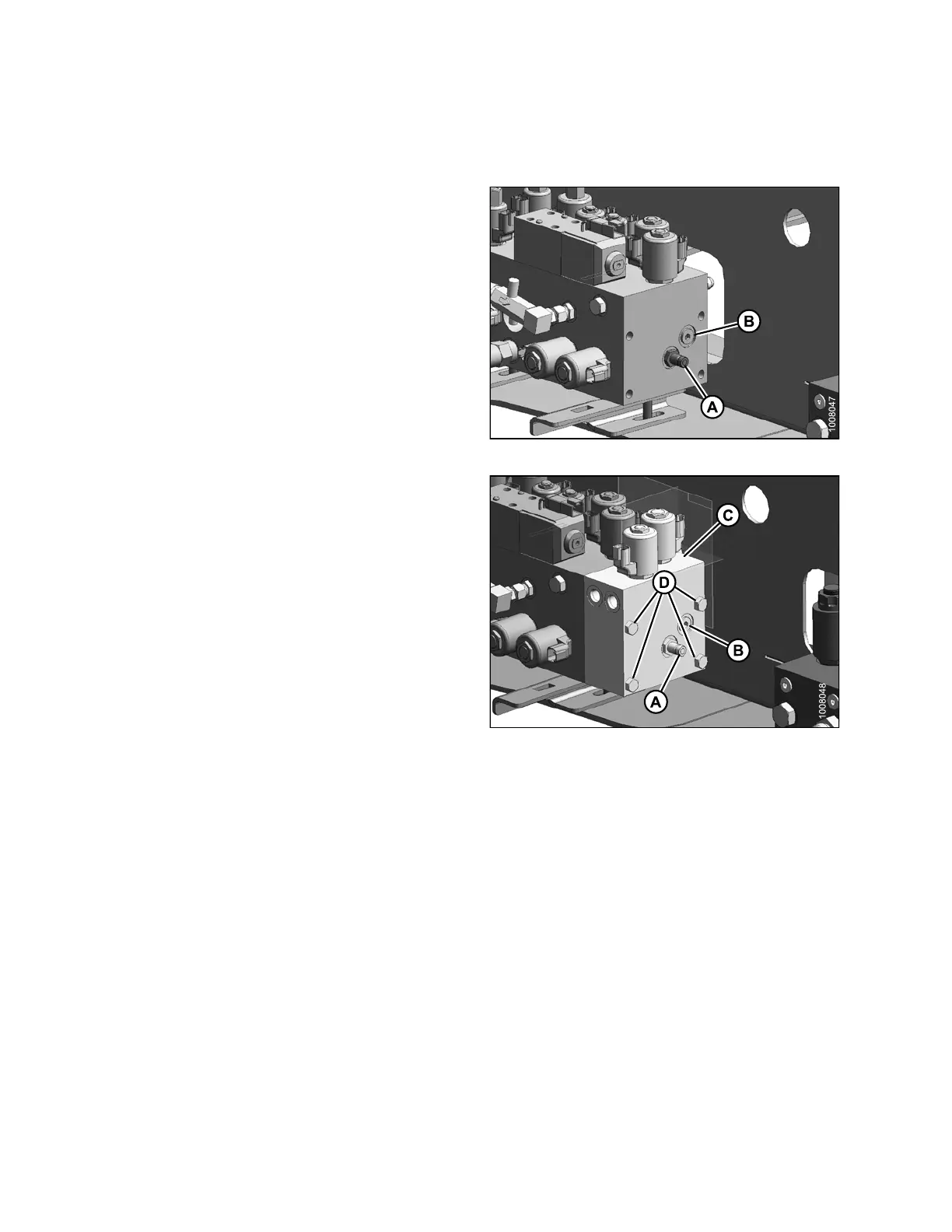
To connect the auxiliary valve blo ck, follow these steps :
1. Remove fitting (A) and plug (B) from the lift manifold
block and reta in for use.
Figure 2.6
5: Lift Manifold Block
2. Attach the auxiliary va lve block (C) to the lift
manifold block.
NOTE:
If instal
ling onto a windrower paired with a
D60 heade
r with reel fore-aft, the windrower
will alr
eady have an auxiliary valve b lock. The
new valv
e block (C) is mounted next to the
existin
g one.
3. Apply g
rease to O-rings (supplied with valve block) and
instal
l them in the countersunk port holes where the
plugs w
ere removed.
4. Assemb
le smooth side of valve (C) to lift valve with four
3/8 in
. bolts (D) provided. Use the longer bolts if there
are tw
o auxilia ry valve block s.
5. Torqu
e bolts to 34 N·m (25 ft·lbf).
6. Repla
ce fitting(A)andplug(B)(removedinStep
1, pa
ge 40) into auxiliary va lve blo ck. If plu g (B ) is
dama
ged on removal, an extra plug is provided in
the k
it.
Figure
2.66: Auxiliary Valve Block
214049 40 Revision A
 Loading...


