ASSEMBLY/SETUP INSTRUCTIONS
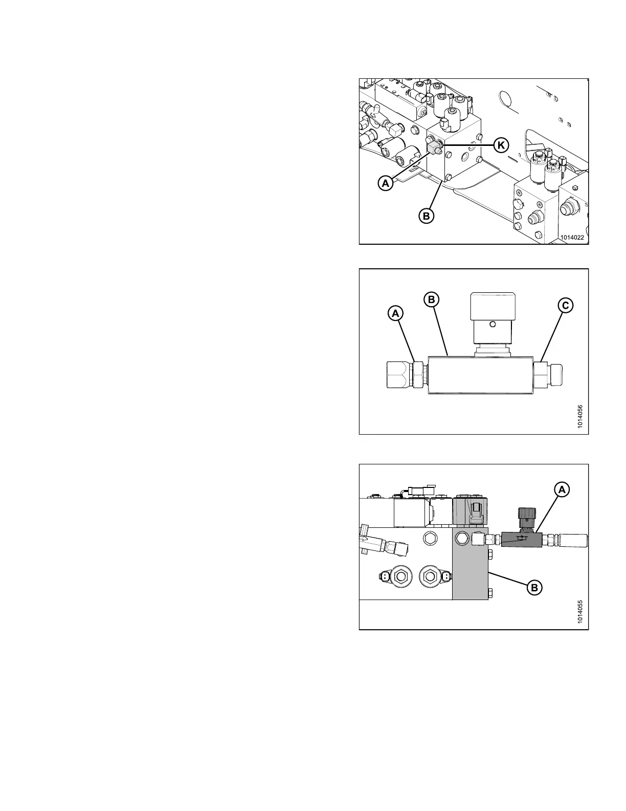
7. Install the 90° elbow fitting (A) into port K on the
auxiliary valve block (B).
Figure 2.67: Auxiliary Valve Block
8. Install the 9/16–18 ORB fitting (A) in to flow valve (B).
9. Install the 3/8 in. tube 37° flare fitting (C) onto the flow
valve (B).
Figure 2.68: Flow Valve
IMPORTAN T:
Orient flow valve a s s hown. The long end of the flow
valve (A) should face the auxiliary valve block (B).
Figu
re 2.69: Flow Valve and Auxiliary Valve
Bloc
k
214049
41
Revision A
 Loading...


