2 Assembly/Setup Instructions
NOTE:
The D ouble Windrow Attachment (DWA) will only fit windrower models listed in the Introduction ( Introduction,
page i). The DWA cannot be installed on the M100 or M105 Self-Propelled Windrower models.
2.1 Reworki
ng Frame for Pre-2008 Windrowers
Before inst
alling the Dou b le Windrow Attachment (DWA) on a windrower built be fore the 2008 production year, follow
these instr
uctions:
1. If holes ar
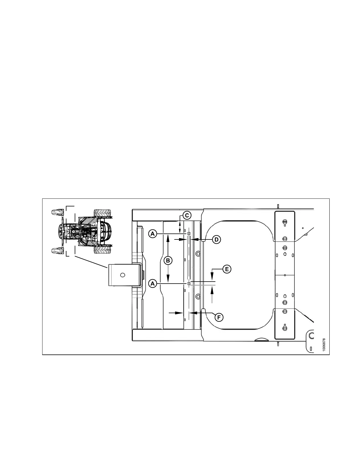
e not present, drill four 20 mm (25/32 in.) diameter holes at the locations shown in Figures 2.1:
Rear-Faci
ng Fr ame, page 11 and 2.2: Forward-Facing Frame, pa ge 12.
IMPORTAN T
:
Move hydr
aulic hoses out of the wa y before d rillin g into the frame at the rear-facing end of the w in drower.
2. Ream/grind rear holes to make them square for square neck bolts.
NOTE:
Slots are only required if holes do not line up with DWA frame.
Figure 2.1: Rear-Facing Frame
A - Hole Locations Rear Frame
B - 480 mm (18-7/8 in.) C - 121.5 mm (4-25/32 in.)
D-
20 mm (25/32 in.)
E-
25 mm (1 in.)
F-
50 mm (1-31/32 in.)
214049
11
Revision A


 To Next Page