ASSEMBLY/SETUP IN STRUC TIONS
2.6.4 Install
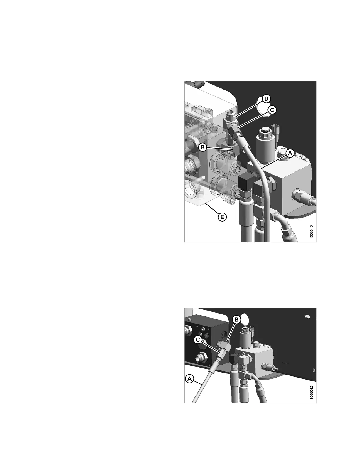
ing Case Drain H ose: M150/M200 and D-Series Headers with
Reverser
To connect the case drain hose to the header drive block, follow these steps:
1. Disconnect the reel return hose connected to port T
and all the fittings in between.
2. Connect #12 ORB x #10 JIC elbow (B) to port T on the
header drive block.
3. Connect #10 JIC tee (D) to elbow (B).
4. Connect #10 JIC x #6 JIC reducer (C) to tee (D).
5. Connect case drain hose (A) to reducer (C).
NOTE:
Make sure hose (A) is not rubbing against
any fittings.
Refer to 5.5 Hydraulics and In-Cab Electrical, page 92
for additional information on the hydraulic connections.
6. Reconne ct the reel return hose by first ins talling elbow
removedearlierinStep1., page 38 to tee (D) followed
by reel retu rn hose.
7. Proceed to 2.7 Installing the Auxiliary Valve Blo ck,
page 40.
Figure 2.62: Header Drive Block
A - Case Drain Hose B - #12 ORB x #10 JIC Elbow
C - #10
JIC x #6 JIC Reducer
D - #10
JIC Tee
E - Reverser (Hidden)
2.6.5 Installing Case Drain Hose: M150/M200 and R-Series Headers
To connect the case drain hose to the header drive block follow these steps:
1. Connect #12 ORB x #10 JIC elbow (B) to port T on the
header drive block.
2. Install #10 JIC x #6 JIC reducer (C) to elbow (B).
3. Install case drain hose (A) to reducer (C).
NOTE:
Make sure hose (A) is not rubbing against
any fittings.
Refer to 5.5 Hydraulics and In-Cab Electrical, page 92
for additional information on the hydraulic connections.
4. Proceed to 2.7 Installing the Auxiliary Valve Blo ck,
page 40.
Figure 2.63: Header Drive Block
214049 38 Revision A

 Loading...


