ASSEMBLY/SETUP IN STRUC TIONS
12. Lowe r linkage b y pulling on safety pin (A) on the
left-hand side of linkage.
13. If the linkage does not lower, remove plugs at the end
of lift cylinder h oses (B) to re move air from hoses.
Figure 2.24: DWA Linkage
14. Secure the lift cylinder pivot (A) into the correct hole
depending on header type:
• For R-Series header: insert pin in the upper hole (B)
• For A-Series or D-Series header: insert pin in the
lower hole (C)
Figure 2.25: Lift Cylinder Pivot
2.4.2 Installing the Linkage: M200
To install the linkage on an M200 windrower, follow
these steps :
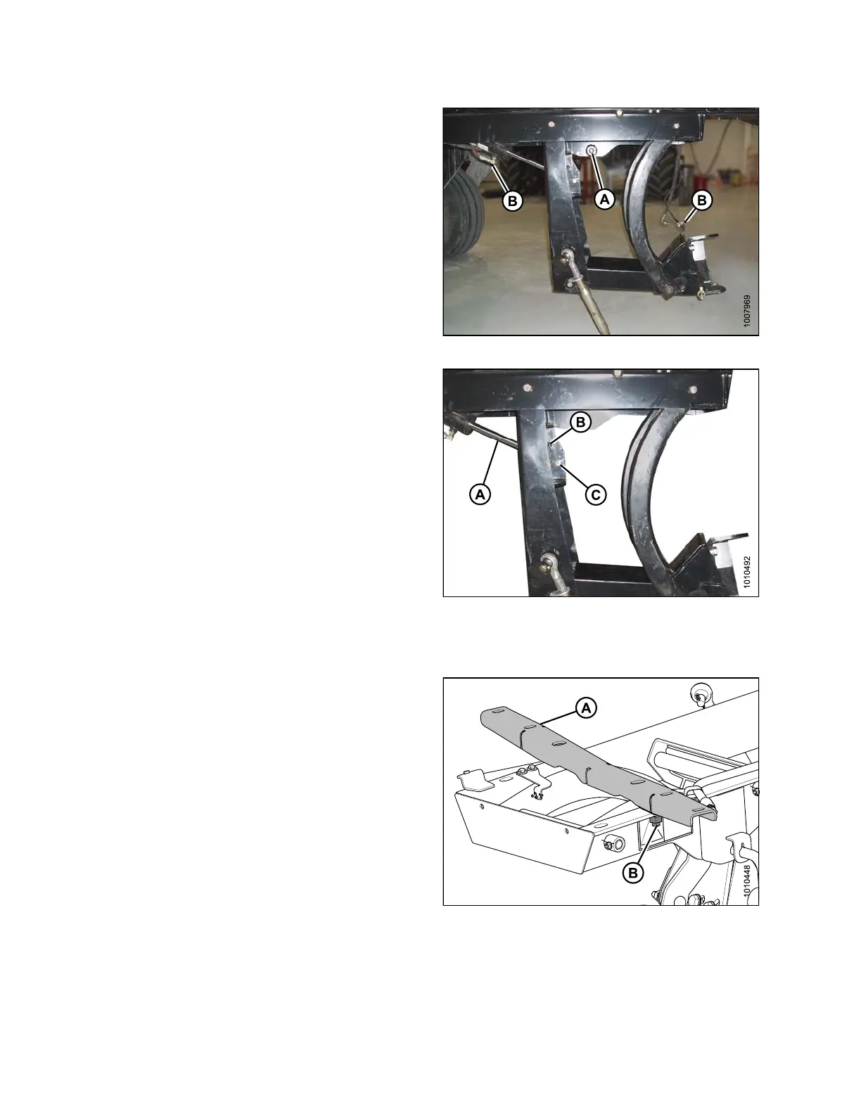
1. Remove support (A) from the DWA linkage by
removing nut (B).
Fig
ure 2.26: DWA Support
214049
22
Revision A
 Loading...


