ASSEMBLY/SETUP INSTRUCTIONS
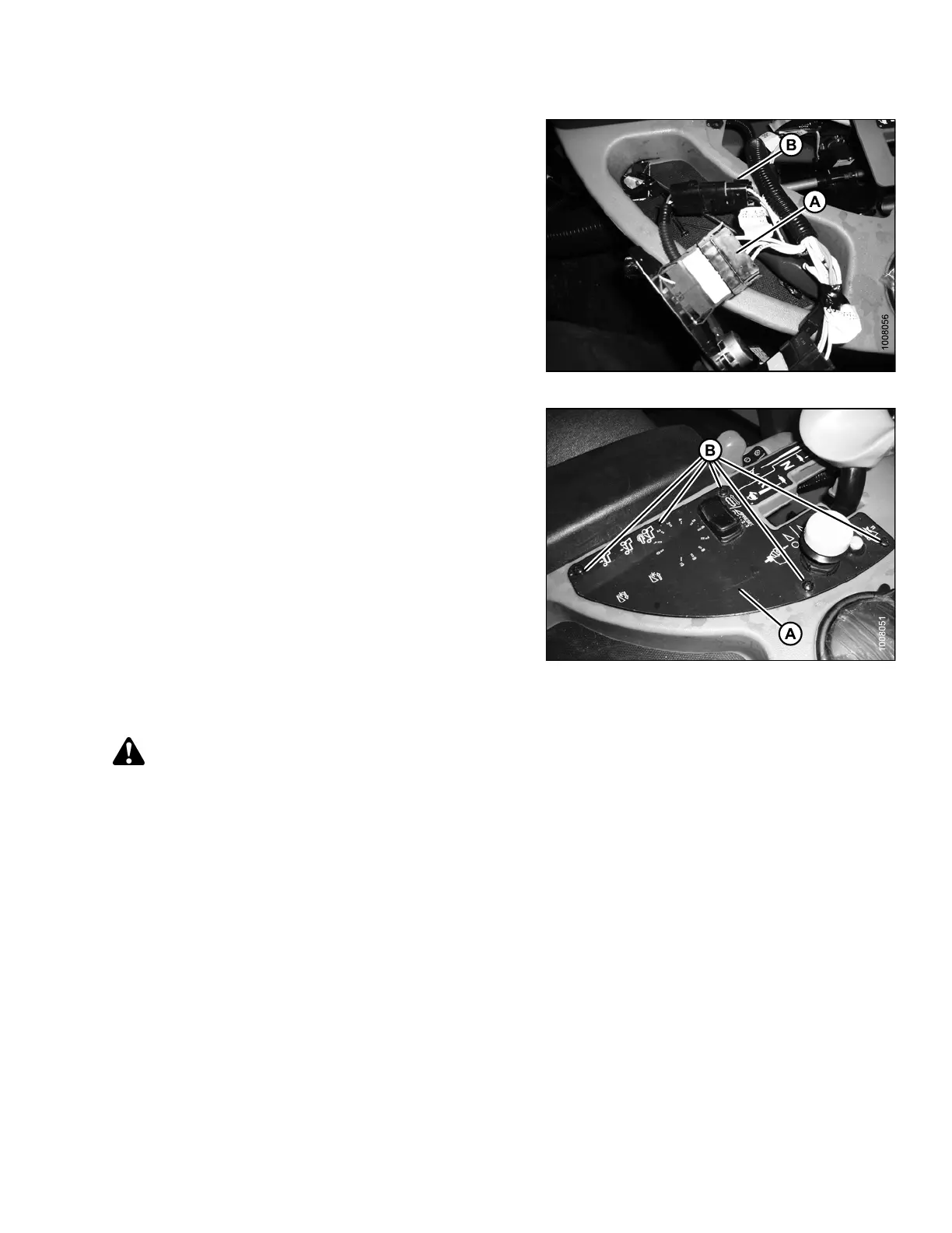
10.Installtherockerswitchintoplug(A)andinstallthe
rotary switch into plug (B). These plugs come prewired
into the w indrower console.
Figure 2.77: DWA Switch
11. Reinstall the cover (A) with five screws (B).
NOTE:
Refer to 2.8.1 Activating the Double Windrow
Attachment (DWA), page 45 to program the cab
display module for control of DWA functions.
Figure 2.78: Console Control Plate
2.8.1 Activating the Double Windro w Attachment (DWA)
CAUTION
Check to be sure all bystanders h a ve cleared the area.
NOTE:
All cab display module images used in this procedure come from an M155 Self-Propelled-Windrower. Other
windrower models are similar.
214049 45 Revision A
 Loading...


