ASSEMBLY/SETUP INSTRUCTIONS
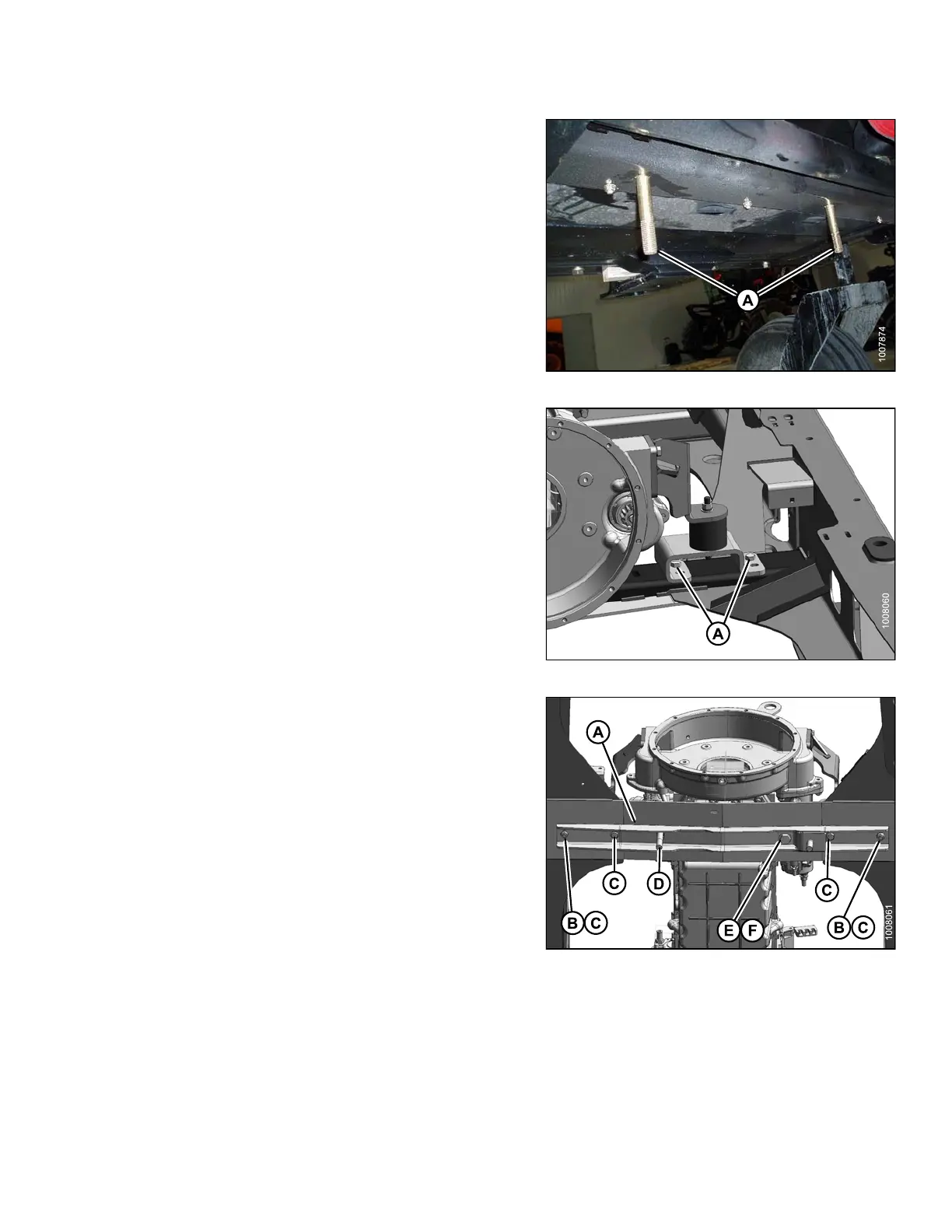
2. Install two 3/4 in. x 4-1/2 in. long carriage head bolts (A)
in the windrower frame member located between the
engine and caster wheels.
NOTE:
Move the hoses located above the frame
member to get the bolts in place.
Figure 2.27: Windrower Frame Member
3. Remove four bolts (A) from the front engine mounts
(two on left side and two on right side). Retain nuts
for reuse.
Figure 2.28: Windrower Engine Mount
4. Mount support (A) to windrower frame with four
1/2 in. x 2-3/4 in. long hex head bolts (C) with flat
washers under the bolt heads and secure with nuts (B).
NOTE:
These b
olts replace the engine mount bolts
remov
ed in Step 3., page 23.
5. From b
elow the support, install a 3/4 in. x 3-1/2 in. long
hex he
ad bolt (E) with flat washer (F) under the
bolt
head.
6. Secu
re with a flat washer, a lock washer, and a nut on
the t
op side of the frame.
7. From
above the support, install a 3/4 in. x 5-1/2 in. long
hex h
ead bolt (D) with flat washer under the bolt head.
Do N
OT install nut on bolt (D).
Figure 2.29: Linkage Support
214049 23 Revision A
 Loading...


