ASSEMBLY/SETUP IN STRUC TIONS
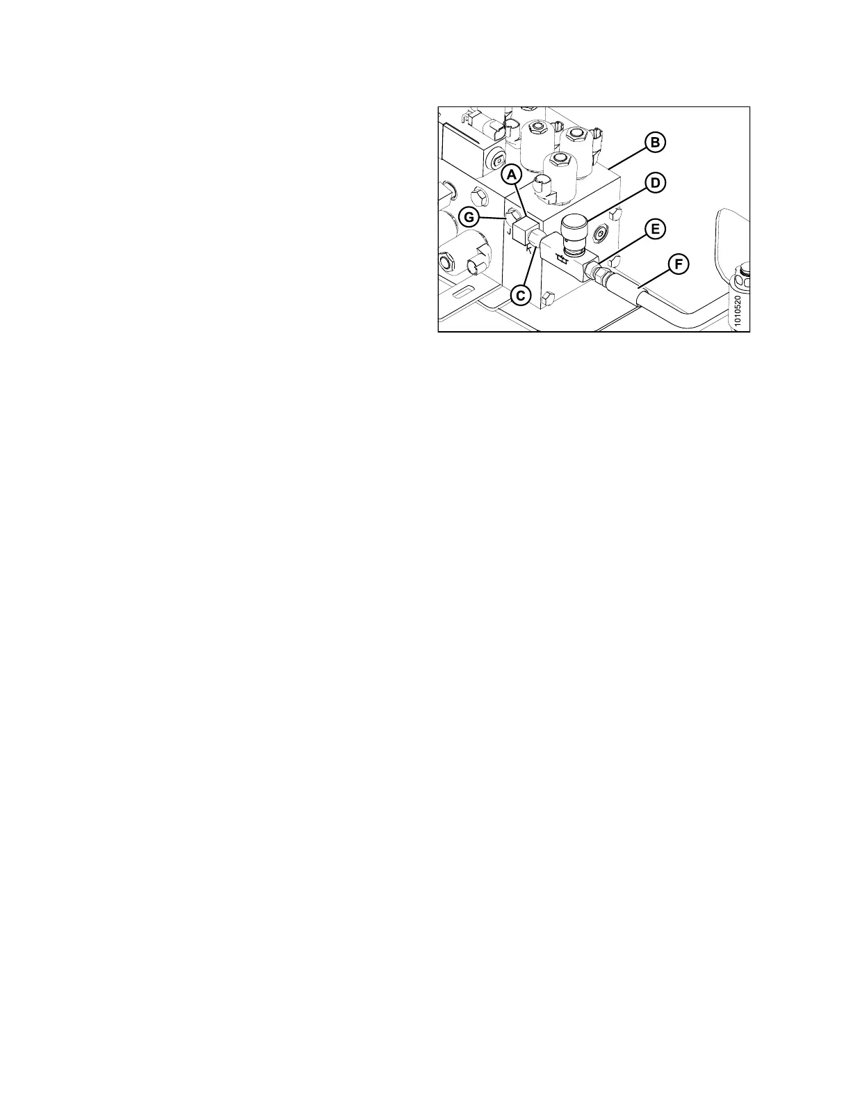
10. Connect the 9/16–18 ORB fitting (C) to the 90° elbow
fitting (A).
11. Route the 1/4 in. lift cylin de r hose (F) through the sid e
of windrower frame and connect to fitting (E).
12. Route the hoses neatly by using the cable ties included
in the kit. Ensure hoses are not rubbing against
moving parts.
13. Install plug (G) into port J on the auxiliary valve
block (B).
Figure 2.70: Auxiliary Valve Block
214049
42
Revision A
 Loading...


