ASSEMBLY/SETUP IN STRUC TIONS
4. Attach the extension hose to the plastic tee fitting using
another larger gear clamp.
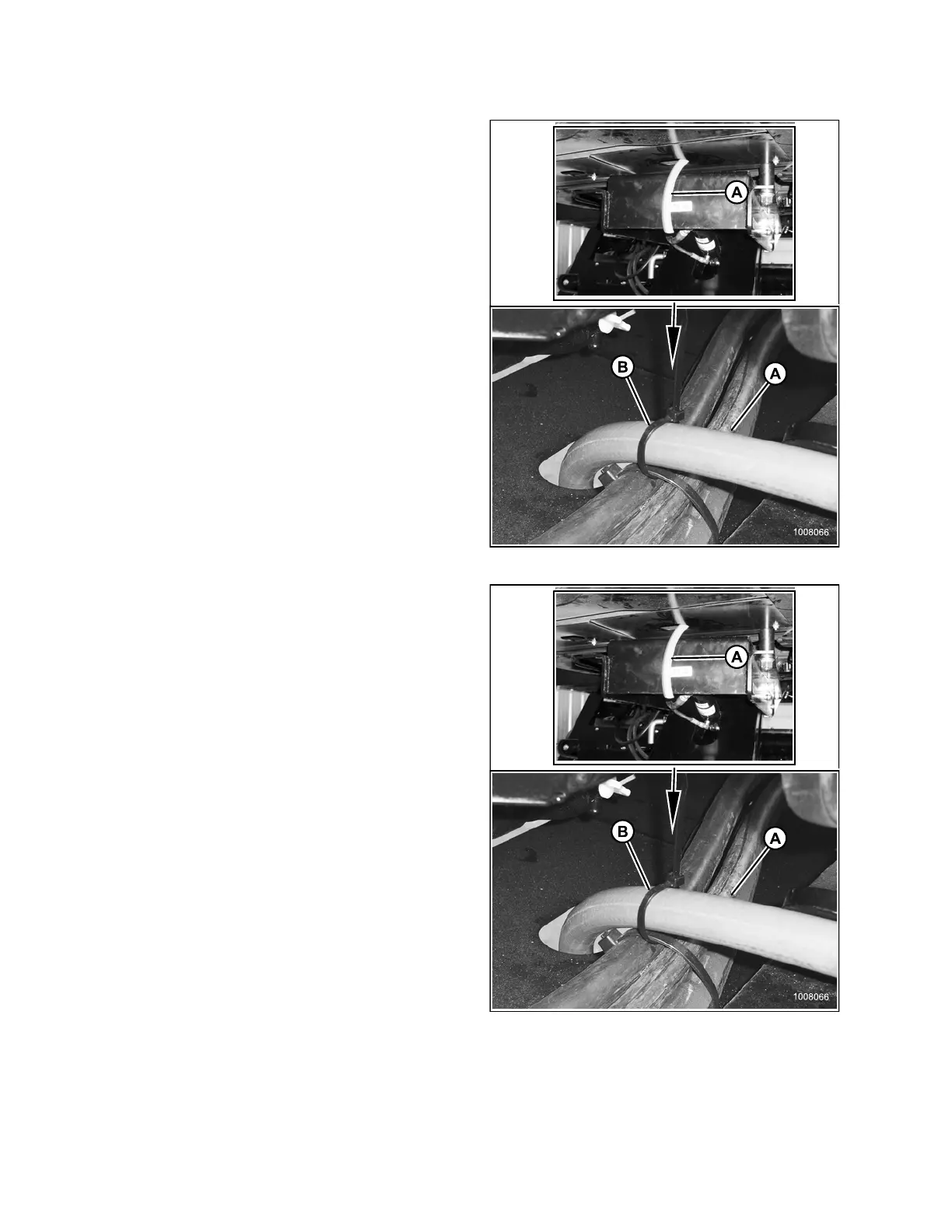
5. Route hose (A) through the slot in frame member and
secure with a cable tie (B) as shown.
Figure 2.
83: Overflow Hose Routing
6. Trim hose (A) to length as follows:
• R-Serie
sRotaryDiscHeader: Leave
approxi
mately180mm(7in.) freehosebelow
windro
wer frame
• ASerie
s Auger and D-Series Draper Header:
Leave a
pproximately 360 mm (14 in.) free hose
below w
indrower frame
Figure 2.84: Overflow Hoses
214049 48 Revision A
 Loading...


