ASSEMBLY/SETUP IN STRUC TIONS
4. Attach the ext ension hose to the union fitting us ing a
larger gear clamp.
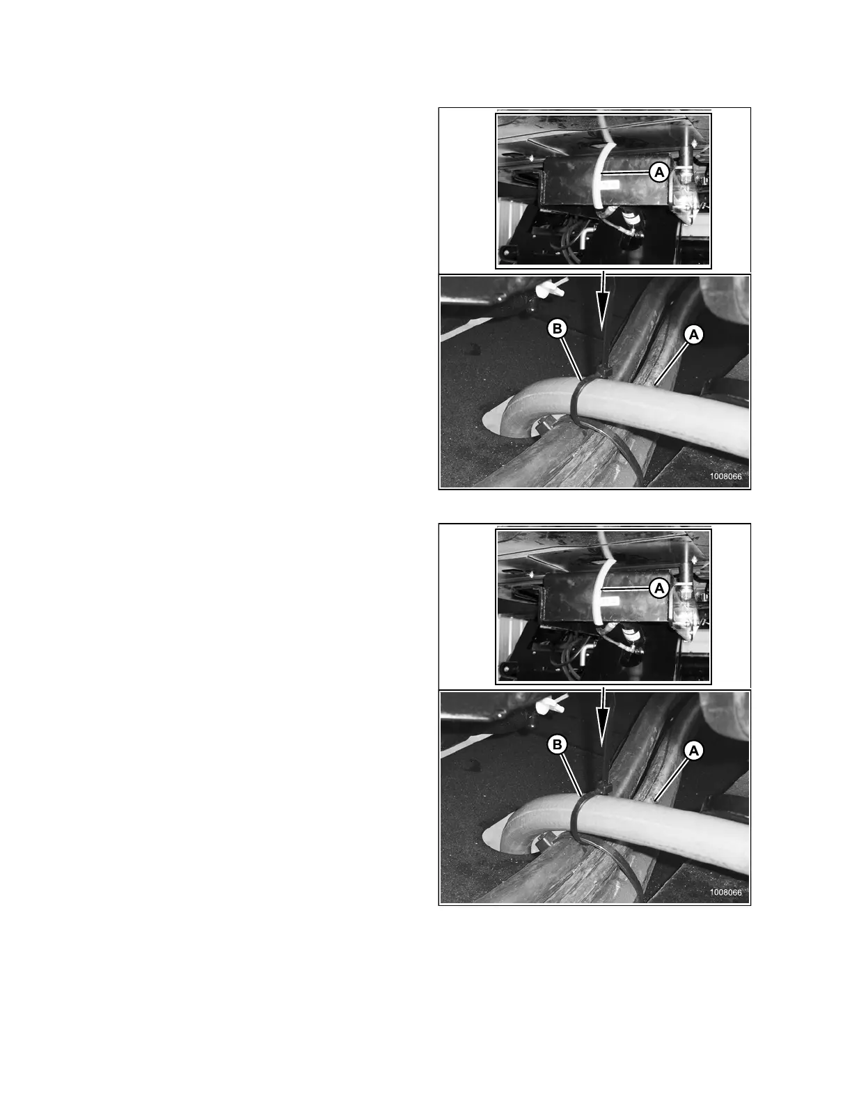
5. Route hose (A) through the slot in frame member and
secure with a cable tie (B) as shown.
Figure 2.
87: Overflow Hoses
6. Trim hose (A) to length as follows:
• R-Serie
sRotaryDiscHeader: Leave
approxi
mately180mm(7in.) freehosebelow
windro
wer frame
• ASerie
s Auger and D-Series Draper Header:
Leave a
pproximately 360 mm (14 in.) free hose
below w
indrower frame
Figure 2.88: Overflow Hoses
214049 50 Revision A
 Loading...


