ASSEMBLY/SETUP IN STRUC TIONS
4. Attach the extension hose to the plastic tee fitting using
another larger gear clamp.
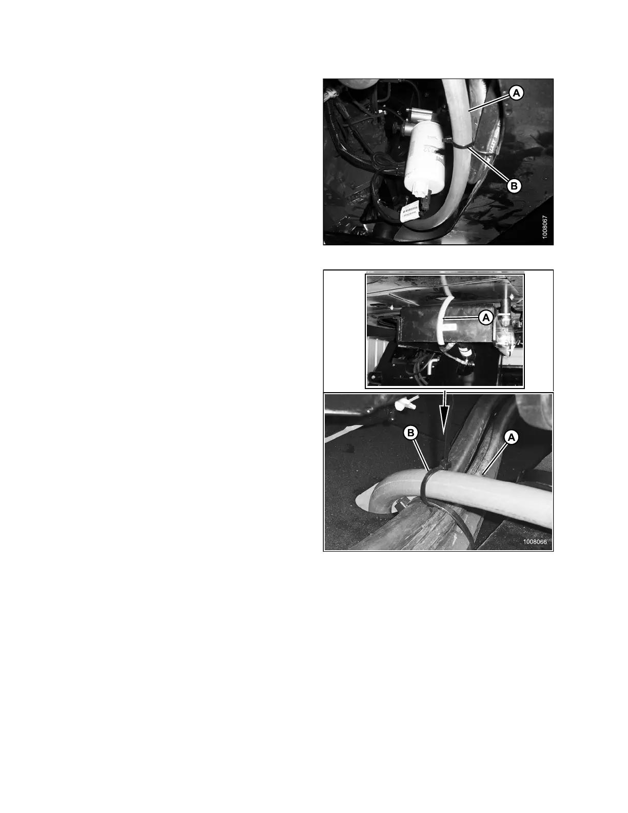
5. Route the exte nsion hose (A) along side of the
windrower frame, and secure to th e existing hoses
with a cable tie (B) as shown.
Figure 2.91: Overflow Hoses
6. Trim hose (A) to length as follows:
• R-Series Rotary Disc Header: Leave
approximately 180 mm (7 in.) free hose below
windrower frame
• A Series Auger and D-Series Draper Header:
Leave approximately 360 mm (14 in.) free hose
below windrower frame
Figur
e 2.92: Overflow Hoses
214049 52 Revision A
 Loading...


