215620 180 Revision A
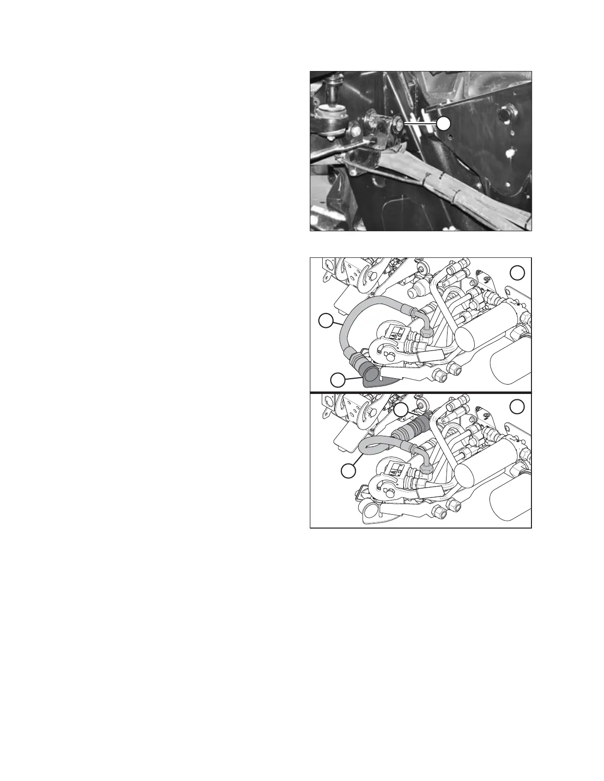
Figure 5.130: Hose Support Attachment
4. Attach hose support (A) to the frame near the windrower
left cab-forward leg, and route the hoses under the frame.
NOTE:
Route the hydraulic hoses as straight as possible, and avoid
rub/wear points that could cause damage.
Figure 5.131: Knife Pressure Hose Positions
1 - Knife Pressure Hose in Storage Position – Rotary Configuration
2 - Hose to Knife Pressure Receptacle – Auger/Draper Configuration
5. If you are switching from an auger/draper header to a
rotary header: Disconnect hose (A) from knife pressure
receptacle (C) on the frame and move it to storage
location (B).
ATTACHING A HEADER TO THE WINDROWER