215620 189 Revision A
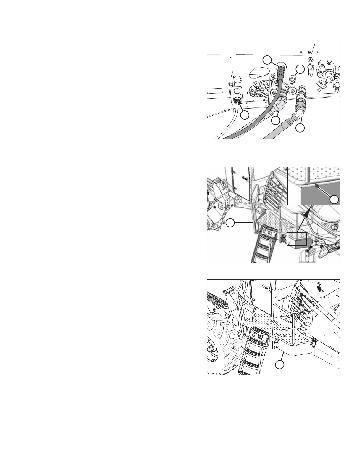
Figure 5.152: Quick Couplers on Rotary Disc Ready
Windrower with Case Drain Kit
5. Connect the hydraulic hoses to the windrower as follows:
a. Connect pressure hose female coupler (A) as shown.
b. Connect return hose male coupler (B) as shown.
c. Connect case drain hose (C) as shown.
NOTE:
The case drain hose coupler will be present only if the
M1240 Low Pressure Case Drain kit (MD #B6698) has
been installed.
IMPORTANT:
Ensure that the case drain hose is connected to
port (C), NOT port (E).
d. Connect the header’s electrical harness to
receptacle (D).
Figure 5.153: Left Cab-Forward Platform
6. Push latch (A) to unlock platform (B).
Figure 5.154: Left Cab-Forward Platform
7. Pull platform (A) towards the cab until it stops and the latch
is engaged.
8. If necessary, calibrate both the knife drive and header position sensors on the windrower. Calibrate both the knife
drive and header position sensors whenever you are:
• Attaching the header to the windrower for the first time
• Changing the speed sensor or hydraulic drive motor on the header
ATTACHING A HEADER TO THE WINDROWER
 Loading...


