IMPULSE®•G+ & VG+ Series 4 Instruction Manual – February 2017
5-59
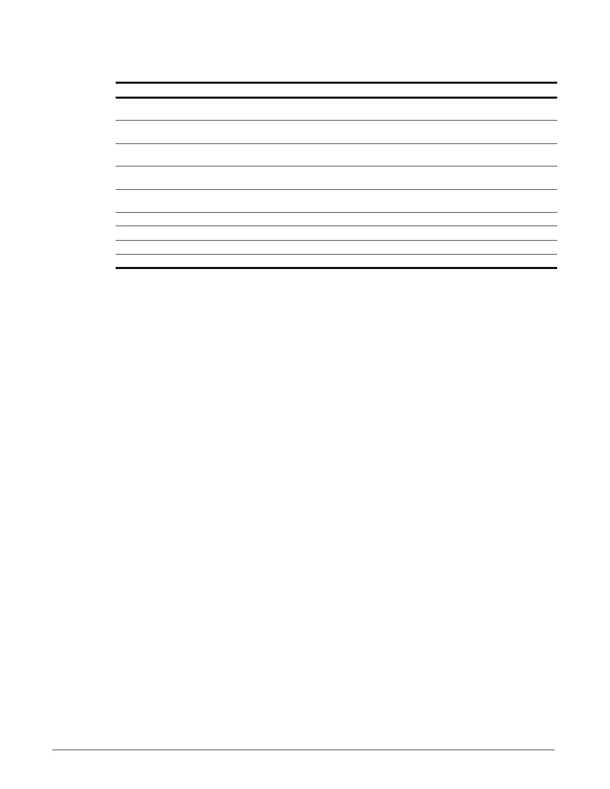
Table 5-47: ASR Tuning Parameter Settings
These parameter settings will function differently depending on the control method.
NOTE: Mechanical backlash in an application can cause secondary current (I
2
) reference
variations in the motor’s rotor. This condition can prevent the desired adjustment of ASR
parameters. The output delay time constant is used to increase the stability of the system
allowing a wider setting range of ASR parameters.
Parameter Display Function Range Default Model
D04-01 ASR P Gain 1 Sets the proportional gain of the
speed control loop (ASR).
0.00–300.00 20.00 VG+
D04-02 ASR I Time 1 Sets the integral time of the speed
control loop (ASR).
0.000–10.000
sec
0.500 VG+
D04-03 ASR P Gain 2 Sets the speed control gain 2 of
the speed control loop (ASR).
0.00–300.00 20.00 VG+
D04-04 ASR I Time 2 Sets the integral time 2 of the
speed control loop (ASR).
0.000–10.000
sec
0.500 VG+
D04-06 ASR Delay Time ASR Output Primary Delay Time. 0.000–0.500
sec
0.004 VG+
D04-07 ASR Gain SW Freq ASR Gain Switching Frequency. 0.0–150.0 Hz 0.0 VG+
D04-08 ASR I Limit ASR Integral Limit. 0–400% 400 VG+
D04-36 NLB Strt ASR I Integral Time at NLB start 0.000–30.000 0.100 VG+
D04-37 NLB Strt ASR Dly ASR Gain Delay at NLB start 0.00–2.55 0.50 VG+

 Loading...


