IMPULSE®•G+ & VG+ Series 4 Instruction Manual – February 2017
5-60
Flux Vector (FLV)
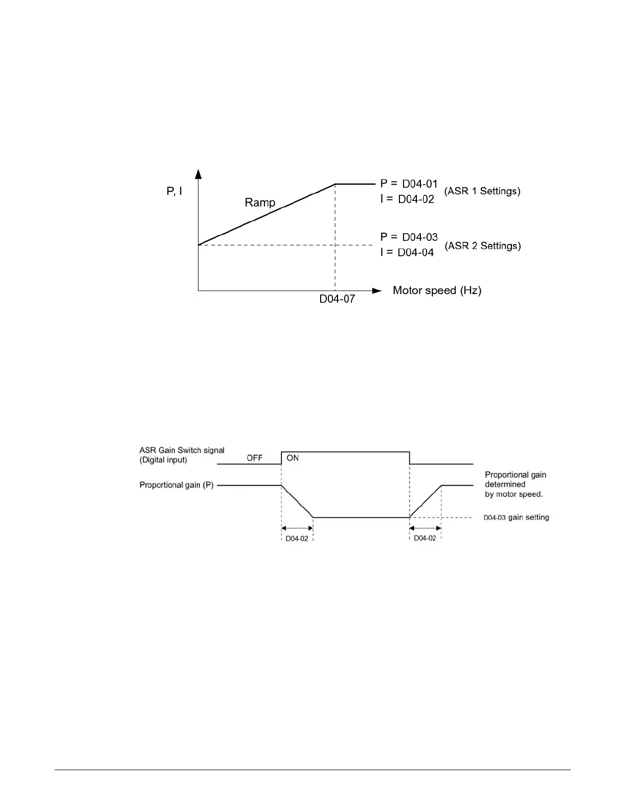
Parameters D04-03 and D04-04 define the ASR proportional gain an integral time at zero speed.
The settings in D04-01 and D04-02 are used at speeds above the setting in D04-07. D04-07 is set
by default to 0.0 so D04-01 and D04-02 are used by default over the entire speed range. However,
changing D04-07 creates two levels of ASR control settings, as shown in Figure 5-19 below.
Figure 5-19: Low-speed and High-speed Gain Settings
The switching frequency (D04-07) can also be controlled with a digital input programmed to “ASR
gain switch” (H01-xx = 37). When the terminal is open, the drive uses the ASR gain level set by the
pattern in Figure 5-19 above. When the terminal closes, D04-03 is used. The integral time set to
D04-02 is used to change linearly between these settings, as shown in Figure 5-20 below. The ASR
gain switch command from a multi-function input terminal overrides the switching frequency set to
D04-07.
Figure 5-20: ASR Proportional Gain Switch

 Loading...


