Home
Man
Engine
B&W S50MC-C8-TII
Page 130 (Centre of Gravity)
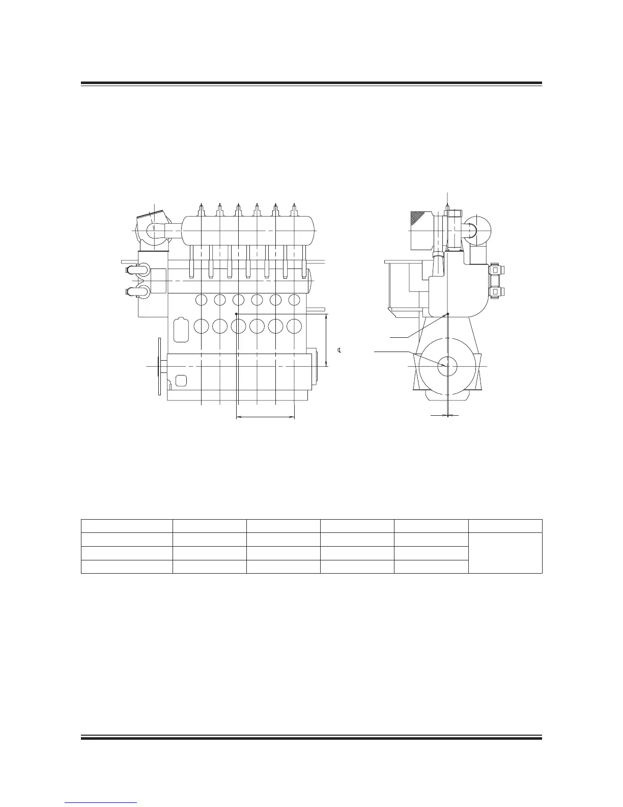
Man B&W S50MC-C8-TII - Centre of Gravity
403 pages
Manual
To Next Page
To Next Page
To Previous Page
To Previous Page
Loading...
MAN B
&W
5.07
Page of
MAN Diesel
MA
N B&
W S5
0M
C-C
7/8
198 6
6 4
8-
6.0
Fig. 5.07
: Ce
ntre o
f gra
vit
y
178 39 52-9.1
#E
NTR
EæOFæGR
AVIT
Y
#R
ANK
SHA
FT
8
9
:
Cent
re of G
ravit
y
No. o
f cy
li
nd
er
s
5
6
7
8
9
Distance X mm
2,230
2,650
3,070
3,500
Available on
request
Distance Y mm
2,390
2,400
2,400
2,400
Distance Z mm
20
20
25
25
All values stated are appr
oximate
129
131
Table of Contents
Main Page
Data Updates
1
Extent of Delivery
1
Electronic Versions
1
Table of Contents
3
Index
11
Calculation of Capacities
11
Engine Layout and Load Diagrams
12
List of Capacities and Cooling Water Systems
14
Propeller Diameter and Pitch, Influence on Optimum Propeller Speed
15
The MC/MC-C Tier II Engine
16
Engine Design
19
The MC/MC-C Tier II Engine
21
Concept of the MC/MC-C Engine
21
Engine Design and IMO Regulation Compliance
21
Engine Type Designation
23
Power, Speed and Lubricating Oil
24
Fuel and Lubricating Oil Consumption
24
Specific Fuel Oil Consumption (SFOC)
25
Lubricating Oil Data
25
Engine Power Range and Fuel Oil Consumption
25
Performance Curves
26
MC Engine Description
27
Bedplate and Main Bearing
27
Frame Box
27
Cylinder Frame and Stuffing Box
27
Cylinder Liner
28
Cylinder Cover
28
Crankshaft
28
Thrust Bearing
28
Tuning Wheel/Torsional Vibration Damper
29
Connecting Rod
29
Piston
29
Piston Rod
29
Auxiliary Blower
30
Exhaust Gas System
30
Exhaust Turbocharger
30
Camshaft and Cams
30
Governor
31
Fuel Oil Pump and Fuel Oil High Pressure Pipes
31
Fuel Valves and Starting Air Valve
31
Starting Air System
31
Exhaust Valve
32
Cylinder Lubrication
32
Manoeuvring System
32
Reversing
32
Piping Arrangements
33
Engine Cross Section of S50MC-C8
34
Engine Layout and Load Diagrams, SFOC
35
Engine Layout and Load Diagrams
37
Propulsion and Engine Running Points
37
Propeller Curve
37
Propeller Design Point
37
Fouled Hull
38
Sea Margin and Heavy Weather
38
Engine Layout (Heavy Propeller)
38
Engine Margin
38
Propeller Diameter and Pitch, Influence on Optimum Propeller Speed
39
Influence of Diameter and Pitch on Propeller Design
39
Constant Ship Speed Lines
40
Layout Diagram and Constant Ship Speed Lines
40
Layout Diagram Sizes
41
Engine Layout Diagram
42
Specified Maximum Continuous Rating (M)
42
Continuous Service Rating (S)
42
Optimising Point (O)
42
Engine Load Diagram
43
Operating Curves and Limits for Continuous Operation
43
Standard Engine Load Diagram
43
Limits for Overload Operation
44
Recommendation
44
Examples of the Use of the Load Diagram
46
Normal Running Conditions
47
Layout Diagram
47
Load Diagram
47
Special Running Conditions
48
Layout Diagram Without Shaft Generator
51
Diagram for Actual Project
53
Specific Fuel Oil Consumption, ME Versus MC Engines
54
SFOC for High Efficiency Turbochargers
55
SFOC at Reference Conditions
56
SFOC Guarantee
56
Examples of Graphic Calculation of SFOC
57
SFOC Calculations for S50MC-C8
58
SFOC for S50MC-C8 with Fixed Pitch Propeller
59
SFOC for S50MC-C8 with Constant Speed
59
SFOC Calculations, Example
60
Fuel Consumption at an Arbitrary Load
62
Emission Control
63
Emission Limits
63
Reduction Methods
63
Turbocharger Selection & Exhaust Gas By-Pass
65
Turbocharger Selection
67
High Efficiency Turbochargers
67
Exhaust Gas Bypass
68
Extreme Ambient Conditions
68
Arctic Running Condition
68
Emergency Running Condition
68
Nox Reduction by SCR
70
Layout of SCR System
71
Electricity Production
73
Electricity Production
75
Power Take off
75
Designation of PTO
77
Pto/Rcf
78
Extent of Delivery for BWIII/RCF Units
79
Additional Capacities Required for BWIII/RCF
80
Kw Generator
81
Engine Preparations for PTO
82
DMG/CFE Generators
85
Standard Engine, with Direct Mounted Generator and Tuning Wheel
86
Diagram of DMG/CFE with Static Converter
86
Static Converter
87
Extent of Delivery for DMG/CFE Units
87
SMG/CFE Generators
87
PTO Type: BW II/GCR
88
Power Take Off/Gear Constant Ratio
88
Tunnel Gear with Hollow Flexible Coupling
89
Generic Outline of BW IV/GCR, Tunnel Gear
89
Auxiliary Propulsion System/Take Home System
90
Waste Heat Recovery Systems (WHR)
91
L16/24 Genset Data
92
L21/31 Genset Data
95
L21/31 Genset Data
96
L23/30H Genset Data
98
L27/38 Genset Data
101
L28/32H Genset Data
104
Installation Aspects
107
Space Requirements and Overhaul Heights
109
Space Requirements for the Engine
109
Overhaul of Engine
109
Space Requirement
110
Crane Beam for Overhaul of Turbocharger
114
Required Height and Distance
114
Required Height and Distance and Weight
114
Crane Beam for Turbochargers
115
Crane Beam for Overhaul of Air Cooler
116
Engine Room Crane
116
Engine Room Crane
118
Overhaul with man B&W Double/Jib Crane
119
MAN B&W Double/Jib Crane
120
Engine Masses and Centre of Gravity
121
Gallery Outline
121
Engine Outline, Galleries and Pipe Connections
121
Engine and Gallery Outline
122
Upper Platform
129
Lower Platform
129
Centre of Gravity
130
Mass of Water and Oil
131
Water and Oil in Engine
131
Engine Pipe Connections
132
Counterflanges
133
Counterflanges
138
Counterflanges, Connection D
140
MAN Diesel Type TCA/TCR
140
ABB Type TPL/A100
141
MHI Type MET
142
Counterflanges, Connection E
143
MAN Diesel Type TCA
143
ABB Type TPL
144
Engine Seating and Holding down Bolts
147
Engine Seating and Arrangement of Holding down Bolts
147
Epoxy Chocks Arrangement
148
Engine Seating Profile
149
Profile of Engine Seating for Engines with Horizontal Oil Outlets
150
Profile of Engine Seating, End Chocks, Option: 4 82 620
151
Profile of Engine Seating, End Chocks, Option: 4 82 610
151
Engine Top Bracing
152
Mechanical Top Bracing
152
Hydraulic Top Bracing
153
Mechanical Top Bracing Stiffener
153
Hydraulic Top Bracing Arrangement
156
Components for Engine Control System
158
Shaftline Earthing Device
159
Scope and Field of Application
159
Design Description
159
Shaftline Earthing Device Installations
160
Connection of Cables for the Shaftline Earthing Device
160
MAN Diesel’s Alpha Controllable Pitch Propeller
162
VBS Type CP Propeller Designation and Range
162
Data Sheet for Propeller
163
Dimension Sketch for Propeller Design Purposes
163
Main Dimensions
164
Propeller Clearance
164
Servo Oil System for VBS Type CP Propeller
165
Hydraulic Power Unit for Alpha CP Propeller
166
Alphatronic 2000 Propulsion Control System
167
MAN Diesel’s Alphatronic 2000 Propulsion Control System
167
Propulsion Control Station on the Main Bridge
168
Main Bridge Station Standard Layout
168
List of Capacities: Pumps, Coolers & Exhaust Gas
171
Calculation of List of Capacities and Exhaust Gas Data
173
Nomenclature
173
Engine Configurations Related to SFOC
173
List of Capacities and Cooling Water Systems
174
Cooling Water Systems
174
Heat Radiation and Air Consumption
174
Flanges on Engine, Etc.
174
Fuel
175
Auxiliary Machinery Capacities
180
Cooler Heat Dissipations
180
Pump Capacities
181
Seawater Cooling System
181
Central Cooling Water System
181
Pump Pressures
181
Calculation of List of Capacities for Derated Engine
182
Freshwater Generator
184
Calculation Method
184
Jacket Cooling Water Temperature Control
185
Calculation of Freshwater Production for Derated Engine
186
Exhaust Gas Amount and Temperature
187
Influencing Factors
187
Summarising Equations for Exhaust Gas Amounts and Temperatures
187
Correction for Engine Load
189
Exhaust Gas Correction Formula
189
Calculation of Exhaust Data for Derated Engine
190
Reference Conditions
190
Final Calculation
191
Exhaust Gas Data at Specified MCR (ISO)
191
The Exhaust Gas Temperature
191
Fuel
193
Pressurised Fuel Oil System
195
Design Parameters
195
Fuel Pumps and Drain
195
Fuel Oil System
196
Fuel Considerations
197
Constant Operation on Heavy Fuel
197
Heating of Fuel Drain Pipe
197
Fuel Flow Velocity and Viscosity
197
Fuel Oil System
197
Fuel Oils
198
Heavy Fuel Oil (HFO)
198
Guiding Heavy Fuel Oil Specification
198
Fuel Oil Pipes and Drain Pipes
199
Fuel Oil and Drain Pipes, Standard Fuel Pump
199
Fuel Oil and Drain Pipes for S50MC-C7/8 with VIT Type Fuel Pump
199
Fuel Oil Pipe Insulation
200
Fuel Oil Pipes and Heating Pipes Together
200
Flanges and Valves
200
Heat Loss in Piping
201
Heat Loss/Pipe Cover
201
Fuel Oil Pipe Heat Tracing
202
Fuel Oil and Lubricating Oil Pipe Spray Shields
202
Spray Shields by Anti-Splashing Tape
202
Spray Shields by Clamping Bands
202
Components for Fuel Oil System
203
Fuel Oil Centrifuges
203
Fuel Oil Supply Pump
203
Fuel Oil Circulating Pump
203
Fuel Oil Heater
204
Fuel Oil Heating Chart
204
Fuel Oil Filter
205
Fuel Oil Venting Box
205
Flushing of the Fuel Oil System
205
Water in Fuel Emulsification
206
Temperature and Pressure
206
Safety System
206
Impact on the Auxiliary Systems
206
Lubricating Oil
209
Lubricating and Cooling Oil System
211
Lubrication of Turbochargers
211
Lubricating and Cooling Oil Pipes
212
Hydraulic Power Supply Unit
213
Lubricating Oil Pipes for Turbochargers
214
MAN Diesel Turbocharger Type TCA
214
ABB Turbocharger Type TPL
214
Mitsubishi Turbocharger Type MET
215
Lubricating Oil Centrifuges and List of Lubricating Oils
216
List of Lubricating Oils
216
Components for Lubricating Oil System
217
Lubricating Oil Pump
217
Lubricating Oil Cooler
217
Lubricating Oil Temperature Control Valve
217
Lubricating Oil Full Flow Filter
218
Flushing of Lube Oil System
218
Lubricating Oil Outlet
219
Lubricating Oil Tank
220
Lubricating Oil Tank, with Cofferdam
220
Lubricating Oil Tank Operating Conditions
221
Crankcase Venting and Bedplate Drain Pipes
222
Crankcase Venting
222
Bedplate Drain Pipes
222
Cylinder Lubrication
223
Cylinder Lubricating Oil System
225
Cylinder Lubricators and Service Tank
225
Cylinder Oils
225
Cylinder Oil Feed Rate (Dosage)
225
MAN B&W Alpha Cylinder Lubrication System
226
System Control Units
226
Alpha Adaptive Cylinder Oil Control (Alpha ACC)
227
Working Principle
227
Basic and Minimum Setting with Alpha ACC
227
Pump Station and man B&W Alpha Cylinder Lubricators on Engine
228
Cylinder Lubricating Oil Supply System for Two Different BN Oils
228
Lubricator Control System
229
Wiring Diagram
230
Mechanical Cylinder Lubricators
231
Load Change Dependent Mechanical Lubrication
231
Piping and Instrumentation for a Mechanical Cylinder Lubricator
231
Cylinder Lubricating Oil Supply System
232
Piston Rod Stuffing Box Drain Oil
233
Stuffing Box Drain Oil System
235
Central Cooling Water System
237
Advantages of the Central Cooling System
239
Disadvantages of the Central Cooling System
239
Components for Central Cooling Water System
241
Seawater Cooling Pumps
241
Central Cooling Water Pumps
241
Central Cooler
241
Jacket Water System
242
Jacket Water Cooling Pump
242
Scavenge Air Cooler
242
Jacket Water Cooler
242
Seawater Cooling
243
Seawater Systems
245
Seawater Cooling Pipes
247
Seawater Cooling Pipes for Engines with One Turbocharger
247
Components for Seawater Cooling System
248
Seawater Thermostatic Valve
248
Jacket Cooling Water System
249
Jacket Cooling Water Pipes
250
Components for Jacket Cooling Water System
251
Jacket Water Preheater
251
Deaerating Tank
251
Temperature at Start of Engine
253
Normal Start of Engine
253
Start of Cold Engine
253
Preheating of Diesel Engine
253
Starting and Control Air
255
Starting and Control Air Systems
257
Components for Starting Air System
258
Starting Air Compressors
258
Starting Air Receivers
258
Reduction Station for Control and Safety Air
258
Starting and Control Air Pipes
259
Starting Air Pipes, Reversible Engine
259
Exhaust Valve Air Spring Pipes
260
Starting Air Pipes, Non-Reversible Engine
260
Air Spring Pipes for Exhaust Valves
260
Electric Motor for Turning Gear
261
Scavenge Air
263
Scavenge Air System
265
Exhaust Gas
265
Auxiliary Blowers
266
Emergency Running
266
Scavenge Air Cooler Requirements
266
Influence of Ambient Temperature Conditions
266
Control of the Auxiliary Blowers
267
Diagram of Auxiliary Blower Control System
267
Operation Panel for the Auxiliary Blowers
268
Scavenge Air Pipes
269
Electric Motor for Auxiliary Blower
270
Scavenge Air Cooler Cleaning System
271
Drain from Water Mist Catcher
271
Auto Pump Overboard System
271
Air Cooler Cleaning Unit
272
Scavenge Air Box Drain System
273
Fire Extinguishing System for Scavenge Air Space
274
Fire Extinguishing Pipes in Scavenge Air Space
275
Exhaust Gas
277
Turbocharger Arrangement and Cleaning Systems
279
Exhaust Gas Pipes
280
Cleaning Systems
281
Exhaust Gas System for Main Engine
282
Exhaust Gas Piping System for Main Engine
282
Components of the Exhaust Gas System
283
Exhaust Gas Compensator after Turbocharger
283
Exhaust Gas Boiler
283
Exhaust Gas System, Two or more Tcs
283
Exhaust Gas Silencer
284
Spark Arrester
284
Calculation of Exhaust Gas BackPressure
285
Exhaust Gas Data
285
Mass Density of Exhaust Gas (Ρ)
285
Exhaust Gas Velocity (V)
285
Measuring Back Pressure
286
Pressure Losses and Coefficients of Resistance in Exhaust Pipes
287
Forces and Moments at Turbocharger
288
Turbocharger(S) Located on Exhaust Side
288
One Turbocharger Located on Aft End
289
Diameter of Exhaust Gas Pipes
291
Engine Control System
293
Manoeuvring Consoles
295
Engine Control System Layout
295
Diagram of Manoeuvring System
296
Manoeuvring System on Engine
297
Shut down System
297
Low Load Operation
297
Control System for Plants with CPP
297
Sequence Diagram
298
Governor Parts and Mode of Operation
300
Governor for ‘Conventional’ Plants
300
Governor for ‘Advanced’ Plants
300
Governor and Remote Control Components
301
Electronic Governor
301
Engine Side Control Console with Diagram
302
Engine Side Control Console, for Reversible Engine
302
Diagram of Engine Side Control Console
302
Engine Side Control Console and Instrument Panel
303
Engine Control Room Console
304
Sequence Diagram for Engines with Fixed Pitch Propeller
305
Controllable Pitch Propeller
306
Engine Control System Interface to Surrounding Systems
307
Alarm System
307
Slow down System
307
Telegraph System
307
Auxiliary Equipment System
308
Power Management System
308
Engine Monitoring
308
Instrumentation
308
Vibration Aspects
309
External Unbalanced Moments
311
2Nd Order Moments on 4, 5 and 6-Cylinder Engines
312
Compensator Solutions
312
Preparation for Compensators
313
Basic Design Regarding Compensators
313
Balancing 1St Order Moments
314
1St Order Moment Compensators
314
Examples of Counterweight
314
Electrically Driven Moment Compensator
315
Compensation of 2Nd Order Vertical External Moments
316
Power Related Unbalance
317
Calculation of External Moments
317
Power Related Unbalance (PRU) Values in Nm/Kw
317
Guide Force Moments
318
Top Bracing
318
Definition of Guide Force Moments
318
Vibration Limits Valid for Single Order Harmonics
319
Vibration Limits
319
Axial Vibrations
321
Torsional Vibrations
321
Undercritical Running
321
Critical Running
322
Overcritical Running
322
External Forces and Moments, S50MC-C8 Layout Point
323
Monitoring Systems and Instrumentation
325
PMI System
328
Measurements
328
PMI Type PT/S Off-Line
328
Cocos-EDS
330
Cocos/Eds Features
330
Connectivity
330
Cocos/Eds Sensor List
331
Alarm – Slow down and Shut down System
332
Basic Safety System Design and Supply
332
Alarm and Slow down System Design and Supply
332
Slow down Functions
332
General Outline of the Electrical System
333
Panels and Sensors for Alarm and Safety Systems
333
Alarms for UMS – Class and man Diesel Requirements
334
Local Instruments
339
Other Alarm Functions
342
Drain Box for Fuel Oil Leakage Alarm
342
Bearing Condition Monitoring
342
Oil Mist Detector
342
Bearing Wear Monitoring System
344
Bearing Temperature Monitoring System
344
Water in Oil Monitoring System
345
Liner Wall Monitoring System
345
Control Devices
346
Identification of Instruments
347
Dispatch Pattern, Testing, Spares and Tools
349
Painting of Main Engine
351
Dispatch Pattern
351
Shop Trials/Delivery Test
351
Spare Parts
352
List of Standard Tools
352
Tool Panels
352
Wearing Parts
352
Specification for Painting of Main Engine
353
Dispatch Pattern, List of Masses and Dimensions
360
Shop Test
364
Minimum Delivery Test
364
EIAPP Certificate
364
List of Spare Parts, Unrestricted Service
365
Additional Spares
366
Large Spare Parts, Dimensions and Masses
375
List of Standard Tools for Maintenance
376
Project Suppport and Documentation
389
Project Support and Documentation
391
Engine Selection Guides
391
Project Guides
391
Computerised Engine Application System (CEAS)
392
Installation Documentation
395
Appendix
399
Symbols for Piping
401
Related product manuals
Man B&W S50ME-B9.3-TII
337 pages
Man B&W S80ME-C7
353 pages
Man B&W L35MC6-TII
375 pages
Man E0834 E302
136 pages
Man E2842 E312
136 pages
Man E2876 E312
136 pages
Man E0836 LE302
90 pages
Man E2876 LE302
136 pages
Man E2876 TE302
136 pages
Man E0834 LE302
90 pages
Man D 2876 LE 201
16 pages
Man D 2876 LE 203
16 pages
 Loading...


