MAN B&W 5.10
Page of 2
MAN Diesel
MAN B&W S50MC-C8
198 60 99-7.0
Refe
rence
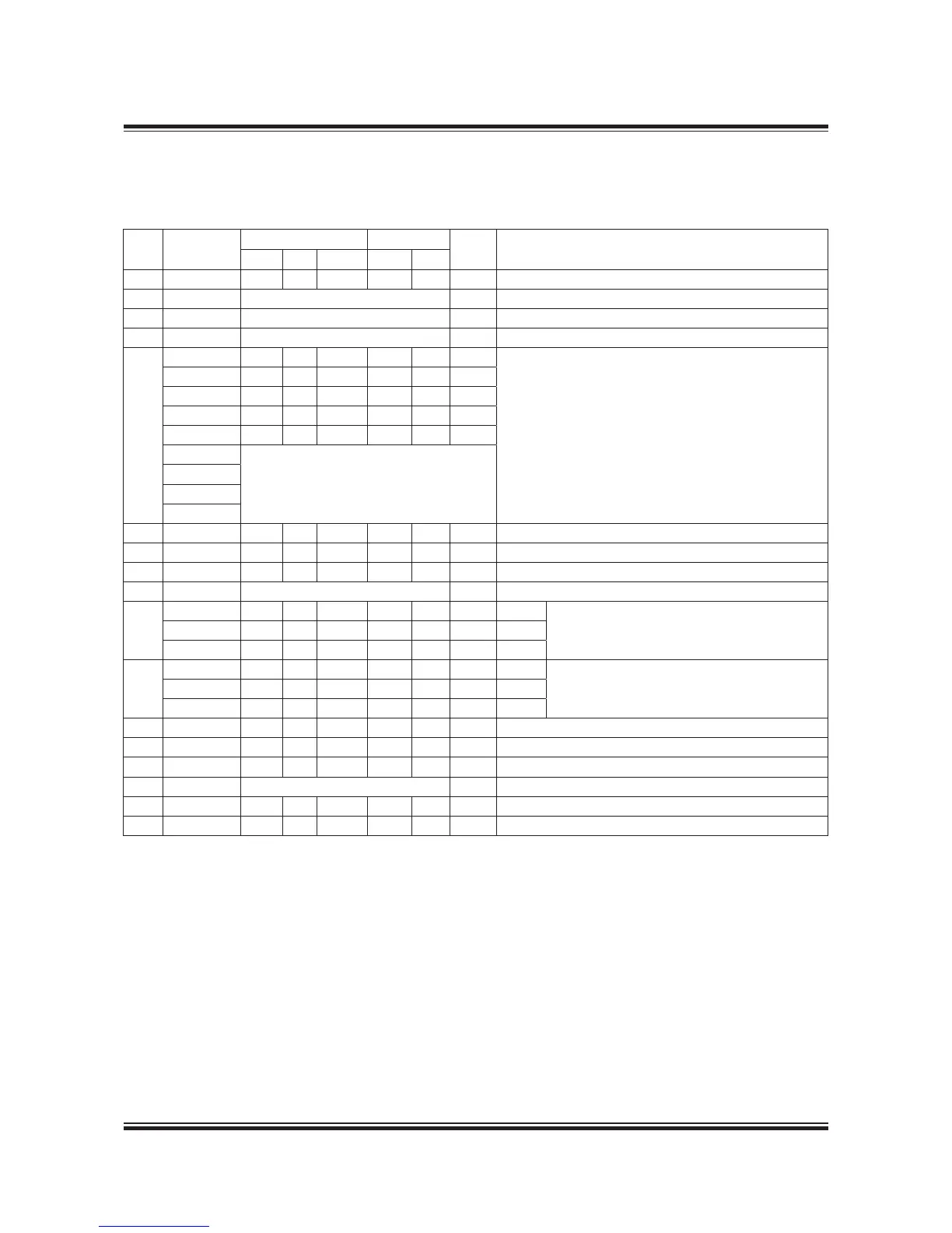
Cyl. no.
Flange Bolts
DN * Description
Diam. PCD Thickn. Diam. No.
A 5-8 235 90 24 M20 8 00 Starting air inlet (Neck ange for welding supplied)
B 5-8 Coupling for 6 mm pipe Control air inlet
C 5-8 Coupling for 6 mm pipe Safety air inlet
D 5-8 See Fig. 5.0.02 Exhaust gas outlet
E
TCA66 200 60 20 M6 8 80
Venting of lub.oil discharge pipe turbocharger
TCA77 200 60 20 M6 8 80
TPL73B-CL 65 25 20 M6 4 50
TPL77B 65 25 20 M6 4 50
TPL80B 85 45 20 M6 8 65
MET53MA
Available on request
MET60MA
MET66MA
MET83MA
F 5-8 50 0 8 M6 4 40 Fuel oil outlet (Neck ange for welding supplied)
K 5-8 220 80 22 M6 8 00 Fresh cooling water inlet
L 5-8 220 80 22 M6 8 00 Fresh cooling water outlet
M 5-8 Coupling for 30 mm pipe Fresh cooling water de-aeration
N
5 285 240 24 M20 8 50 AC:JU
Sea cooling water inlet to air cooler6-7 340 295 24 M20 8 200 AC:JT
8 - - - - - - AC:AC
P
5 285 240 24 M20 8 50 AC:JU
Sea cooling water outlet from air cooler6-7 340 295 24 M20 8 200 AC:JT
8 - - - - - - AC:AC
N 5-8 285 240 24 M20 8 50 Central cooling water inlet to air cooler
P 5-8 285 240 24 M20 8 50 Central cooling water outlet from air cooler
RU 5-8 340 295 24 M20 8 200 Lubricating oil inlet (System oil)
S 5-8 See special drawing of oil outlet System oil outlet to bottom tank (Vertical)
S
5-8 540 495 28 M20 6 400 System oil outlet to bottom tank (Horisontal) (Option)
X 5-8 85 45 22 M6 8 65 Fuel oil inlet (Neck ange for welding supplied)
Counteranges
 Loading...


