MAN B&W 15.06
Page of 3
MAN Diesel
198 40 68-7.1
MAN B&W S50MC-C7/8, S50ME-C7/8
Forces and Moments at Turbocharger
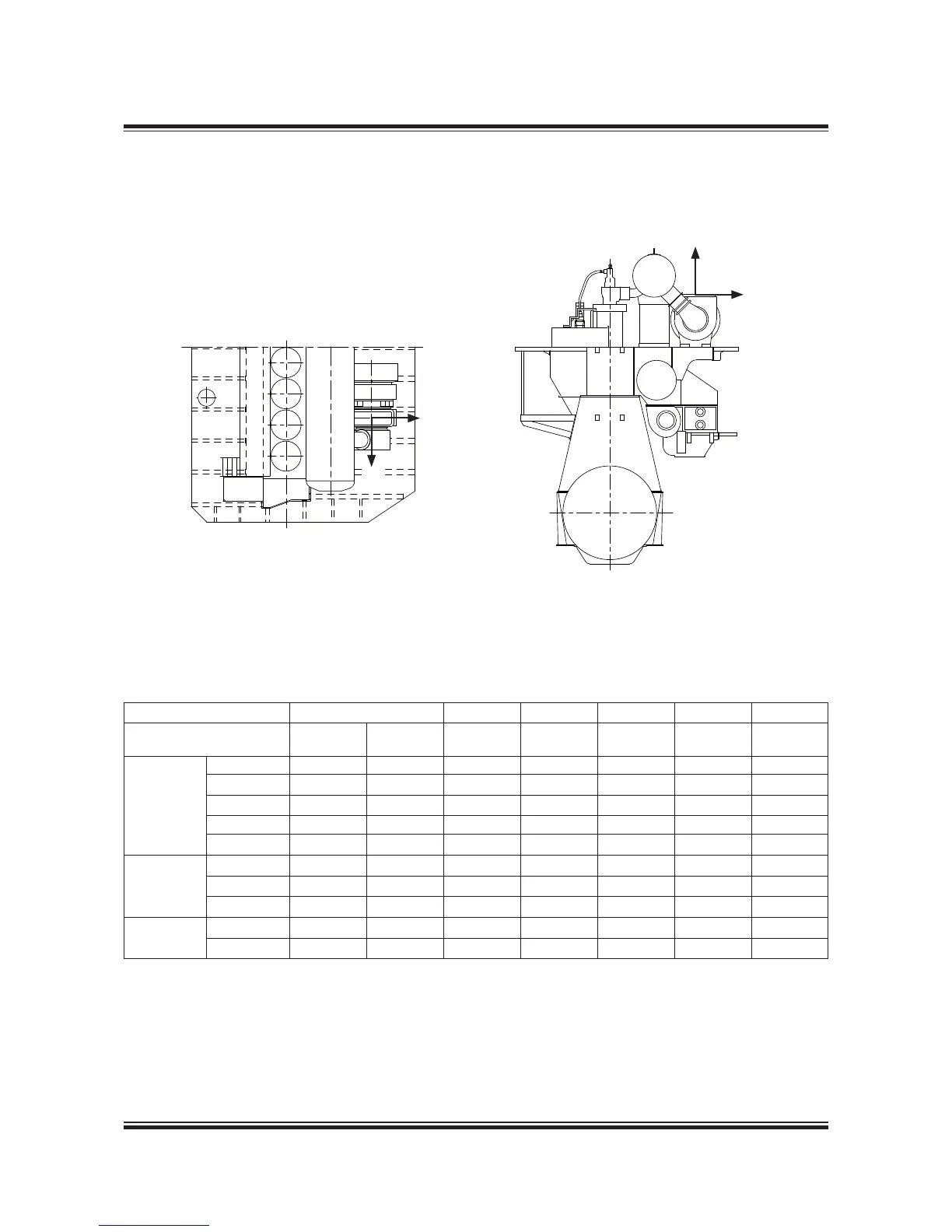
Turbocharger(s) located on exhaust side
Fig. 15.06.01a: Vectors of thermal expansion at the turbocharger exhaust gas outlet ange, TC on exhaust side
078 87 11-1.0.0b
Table 15.06.02a: Max. expected movements of the exhaust gas ange resulting from thermal expansion, TC on exhaust side
No. of cylinders 5-9 5 6 7 8 9
Turbocharger DA DB DC DC DC DC DC
Make Type mm mm mm mm mm mm mm
MAN Diesel
TCA66 7.4 .2 . .3 .4 .6 *
TCA77 8.6 .2 . .3 .4 .6 *
NA48 7.0 .2 . .3 .4 .6 *
NA57 7.4 . . .3 .4 .6 *
NA70 8.8 .3 . .3 .4 .6 *
ABB
TPL73 6.2 . . .3 .4 .6 *
TPL77 6.8 .2 . .3 .4 .6 *
TPL80 7.4 . . .3 .4 .6 *
MHI
MET53 6.5 . . .3 .4 .6 *
MET66 7.3 .2 . .3 .4 .6 *
*) Data is available on request
DA: Max. movement of the turbocharger ange in the vertical direction
DB: Max. movement of the turbocharger ange in the transversal direction
DC: Max. movement of the turbocharger ange in the longitudinal direction
 Loading...


