MAN B&W 5.03
Page 1 of 4
MAN Diesel
MAN B&W S50MC-C/ME-C7/8 198 44 94-0.2
Crane beam for overhaul of turbocharger
For the overhaul of a turbocharger, a crane beam
with trolleys is required at each end of the turbo-
charger.
Two trolleys are to be available at the compressor
end and one trolley is needed at the gas inlet end.
Crane beam no. 1 is for dismantling of turbo-
charger components.
Crane beam no. 2 is for transporting turbocharger
components.
See Figs. 5.03.01a and 5.03.02.
The crane beams can be omitted if the main en-
gine room crane also covers the turbocharger
area.
The crane beams are used and dimensioned for
lifting the following components:
• Exhaust gas inlet casing
• Turbocharger inlet silencer
• Compressor casing
• Turbine rotor with bearings
178 52 340.1
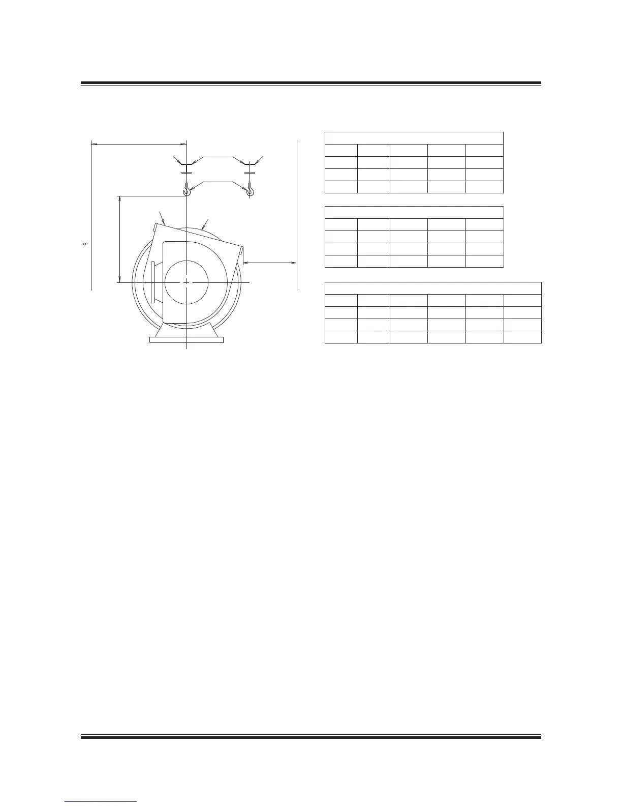
Fig. 5.03.01a: Required height and distance
The crane beams are to be placed in relation
to the turbocharger(s) so that the components
around the gas outlet casing can be removed in
connection with overhaul of the turbocharger(s).
The crane beam can be bolted to brackets that
are fastened to the ship structure or to columns
that are located on the top platform of the engine.
The lifting capacity of the crane beam for the
heaviest component ‘W’, is indicated in Fig.
5.03.01b for the various turbocharger makes. The
crane beam shall be dimensioned for lifting the
weight ‘W’ with a deflection of some 5 mm only.
HB indicates the position of the crane hook in the
vertical plane related to the centre of the turbo-
charger. HB and b also specifies the minimum
space for dismantling.
For engines with the turbocharger(s) located on
the exhaust side, EoD No. 4 59 122, the letter
‘a’ indicates the distance between vertical cen-
trelines of the engine and the turbocharger.
Crane beam
Turbocharger
Gas outlet flange
a
HB
Main engine/aft cylinder
Crane hook
b
Engine room side
Crane beam for
dismantling of
components
Crane beam for
transportation of
components
Fig. 5.03.01b: Required height and distance and weight
The figures ‘a’ are stated on the ‘Engine and Gallery Outline’
drawing, Section 5.06.
MAN B&W
Units TCA55 TCA66 TCA77
W
kg 1,000 1,200 2,000
HB
mm 1,400 1,600 1,800
b
m 600 700 800
ABB
Units TPL73 TPL77 TPL80
W
kg 1,000 1,000 1,500
HB
mm 1,400 1,550 1,900
b
m 600 700 800
Mitsubishi
Units MET53 MET60 MET66 MET71
W
kg 1,000 1,000 1,500 1,800
HB
mm 1,500 1,600 1,800 1,800
b
m 700 700 800 800
 Loading...


