MAN B&W MC/MCC, ME/MEC/MEGI/ME-B engines 198 46 725.8
MAN B&W 5.13
Page 2 of 2
MAN DieselMAN Diesel
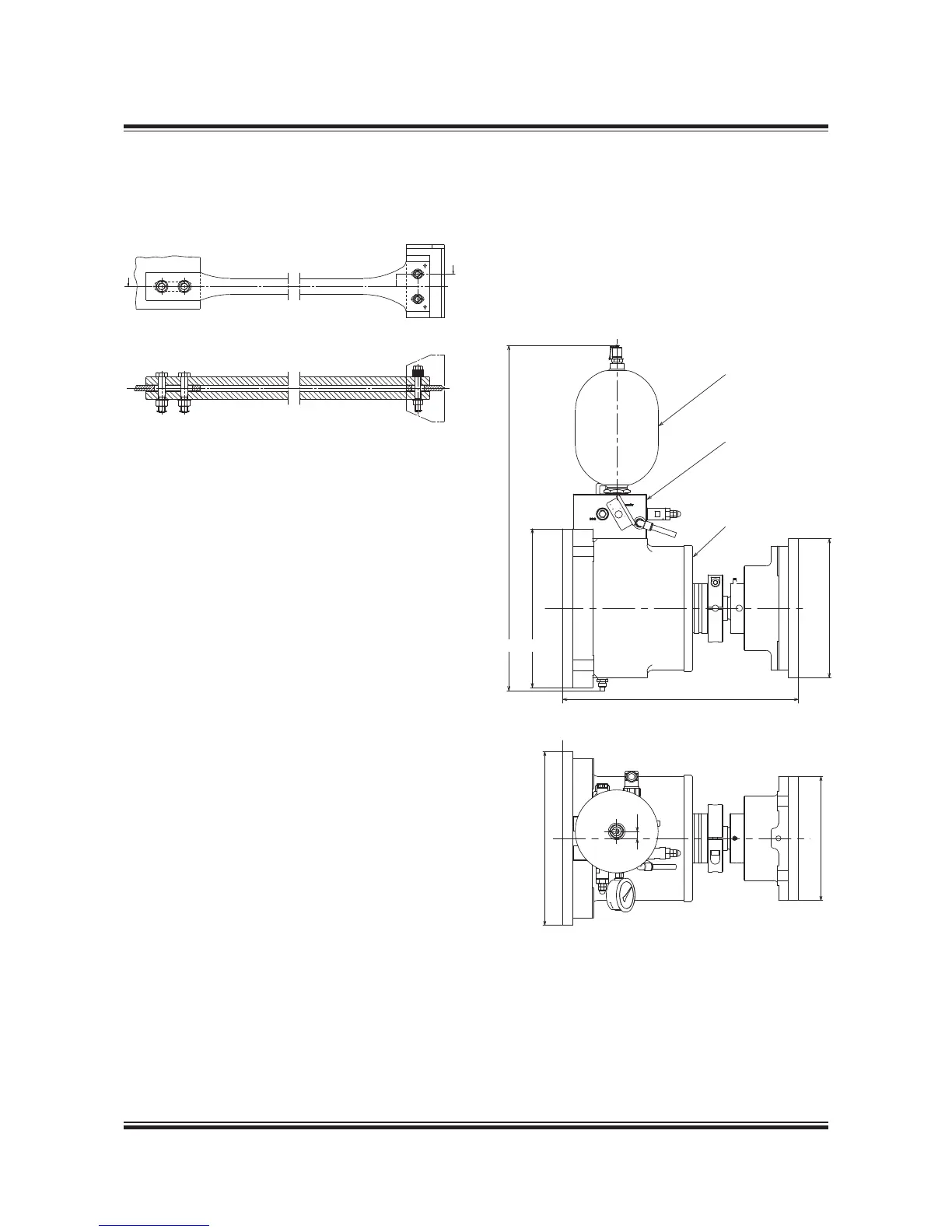
The mechanical top bracing is to be made by the
shipyard in accordance with MAN Diesel instruc-
tions.
178 23 61-6.1
Fig. 5.13.01: Mechanical top bracing stiffener.
Option: 4 83 112
Hydraulic top bracing
The hydraulic top bracing is an alternative to the
mechanical top bracing used mainly on engines
with a cylinder bore of 50 or more. The installation
normally features two, four or six independently
working top bracing units.
The top bracing unit consists of a single-acting hy-
draulic cylinder with a hydraulic control unit and an
accumulator mounted directly on the cylinder unit.
The top bracing is controlled by an automatic
switch in a control panel, which activates the top
bracing when the engine is running. It is possi-
ble to programme the switch to choose a certain
rpm range, at which the top bracing is active. For
service purposes, manual control from the control
panel is also possible.
When active, the hydraulic cylinder provides a
pressure on the engine in proportion to the vibra-
tion level. When the distance between the hull and
engine increases, oil flows into the cylinder under
pressure from the accumulator. When the dis-
tance decreases, a non-return valve prevents the
oil from flowing back to the accumulator, and the
pressure rises. If the pressure reaches a preset
maximum value, a relief valve allows the oil to flow
back to the accumulator, hereby maintaining the
force on the engine below the specified value.
By a different pre-setting of the relief valve, the
top bracing is delivered in a low-pressure version
(26 bar) or a high-pressure version (40 bar).
The top bracing unit is designed to allow dis-
placements between the hull and engine caused
by thermal expansion of the engine or different
loading conditions of the vessel.
178 57 48-8.0
Fig. 5.13.02: Outline of a hydraulic top bracing unit.
The unit is installed with the oil accumulator pointing
either up or down. Option: 4 83 123
AA
 Loading...


