MAN B&W 5.14
Page of 2
MAN Diesel
MAN B&W S50MC-C7/8 198 60 06-4.0
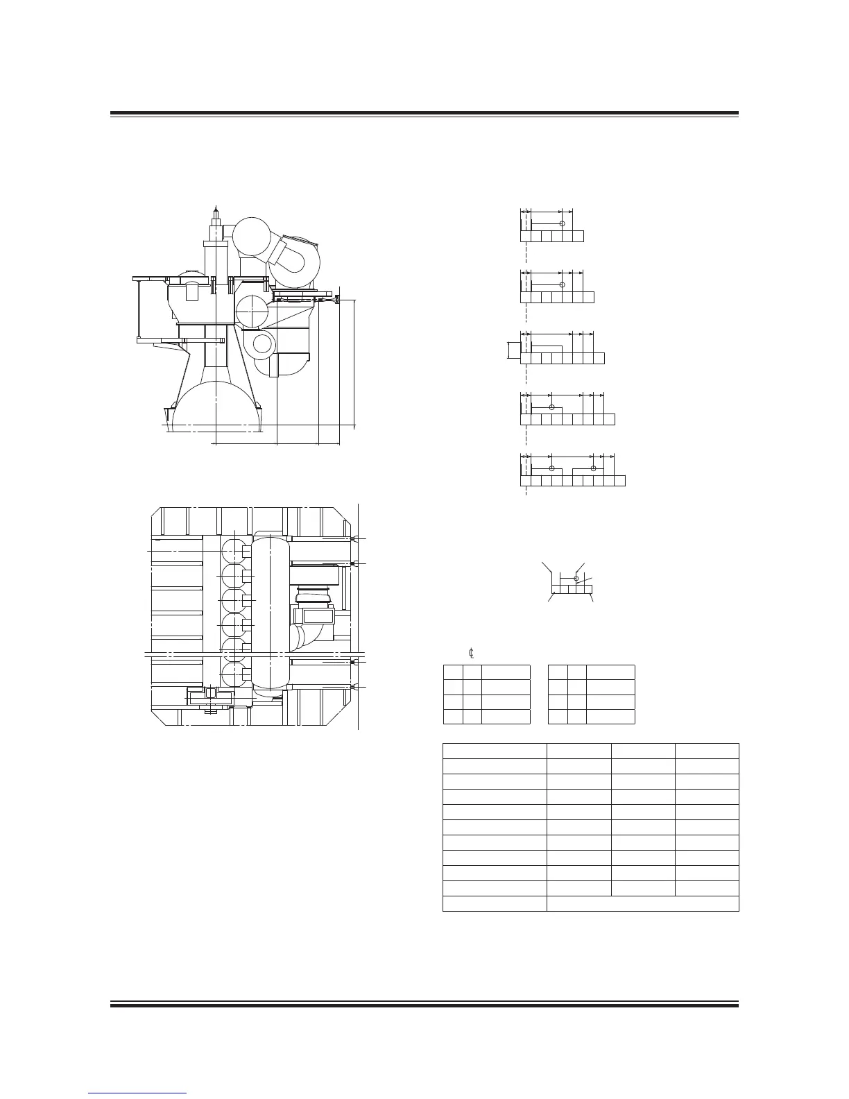
Mechanical Top Bracing
The forces and deections for calculating the
transverse top bracing’s connection to the hull
structure are:
Force per bracing ....................................... ± 28 kN
Minimum horizontal rigidity at the link’s
points of attachment to the hull ............. 20 MN/m
Tightening torque at hull side ......................20 Nm
Tightening torque at engine side ............... 470 Nm
a = 425
c = 2,25
d = 2,975
e = 3,825
f = 4,675
g = 5,525
h = 6,375
k = 7,225
178 38 91-7.3
Fig. 5.14.01: Mechanical top bracing arrangement, exhaust side
Turbocharger Q R U *)
TCA55 3,540 4,80 4,80
TCA66 3,540 4,30 4,80
TCA77 3,540 4,580 4,580
TPL73B 3,355 4,80 4,80
TPL77B 3,540 4,30 4,80
TPL80B 3,540 4,580 4,580
MET53MA 3,370 4,80 4,80
MET60MA 3,540 4,580 4,580
MET66MA 3,765 4,580 4,580
MET7MA
Available on request
*) U: In case of all top bracings are attached at
point P, the minimum attaching point ‘R’ could
be reduced to ‘U’.
Horizontal distance between top bracing x point
and cylinder :
 Loading...


