MAN B&W 7.05
Page 2 of 3
MAN Diesel
MAN B&W MC/MC-C, ME/MEC/MEGI/ME-B engines 198 39 512.6
The heater is to be of the tube or plate heat ex-
changer type.
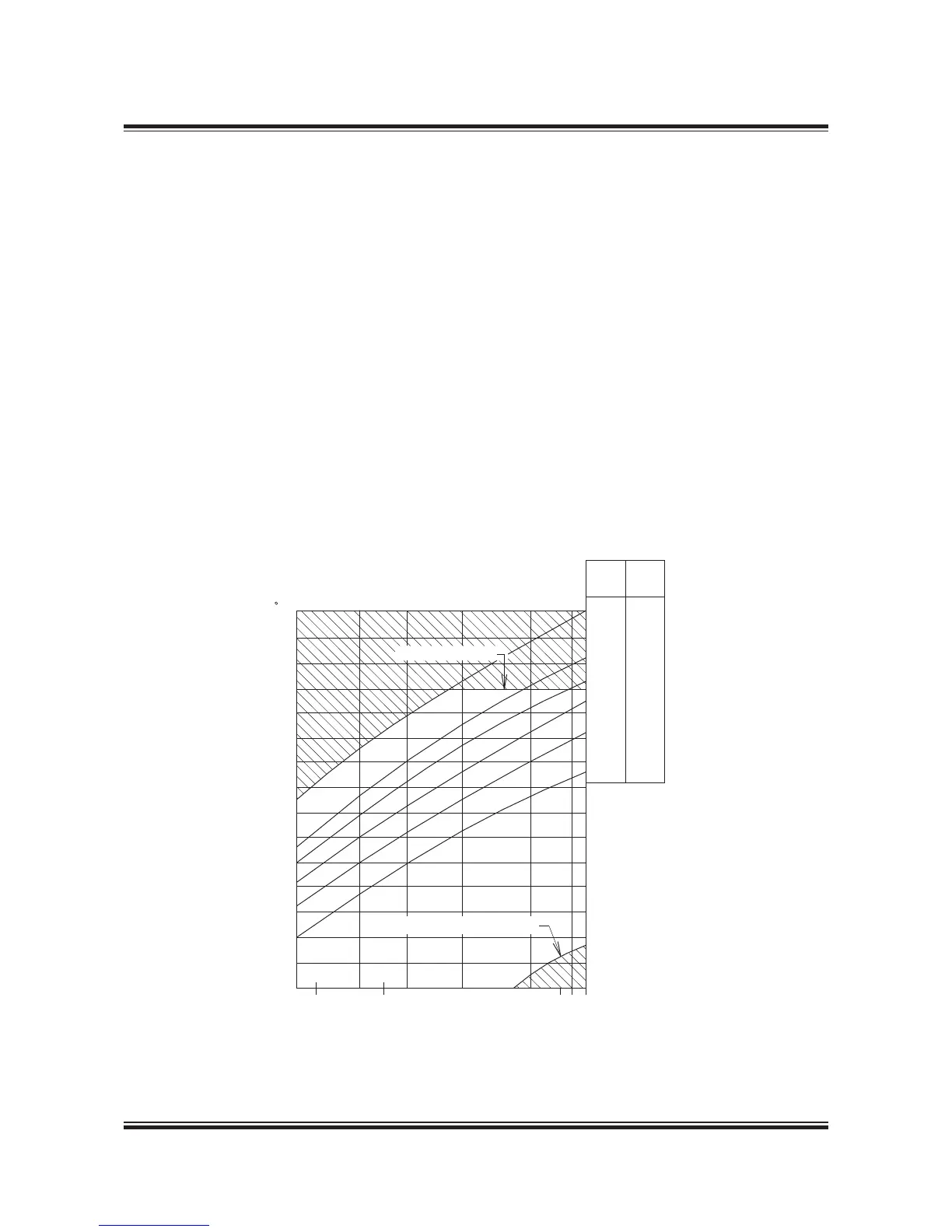
The required heating temperature for different oil
viscosities will appear from the ‘Fuel oil heating
chart’, Fig. 7.05.01. The chart is based on informa-
tion from oil suppliers regarding typical marine
fuels with viscosity index 7080.
Since the viscosity after the heater is the control-
led parameter, the heating temperature may vary,
depending on the viscosity and viscosity index of
the fuel.
Recommended viscosity meter setting is 1015 cSt.
Fig. 7.05.01: Fuel oil heating chart
Fuel oil viscosity specified ... up to 700 cSt at 50°C
Fuel oil flow .................................... see capacity of
fuel oil circulating pump
Heat dissipation ................. see ‘List of Capacities’
Pressure drop on fuel oil side ........maximum 1 bar
Working pressure ..........................................10 bar
Fuel oil inlet temperature .................approx. 100 °C
Fuel oil outlet temperature ........................... 150 °C
Steam supply, saturated ..........................7 bar abs
To maintain a correct and constant viscosity of
the fuel oil at the inlet to the main engine, the
steam supply shall be automatically controlled,
usually based on a pneumatic or an electrically
controlled system.
 Loading...


