MAN B&W 5.12
Page of 4
MAN Diesel
MAN B&W S50MC-C 198 58 60-0.0
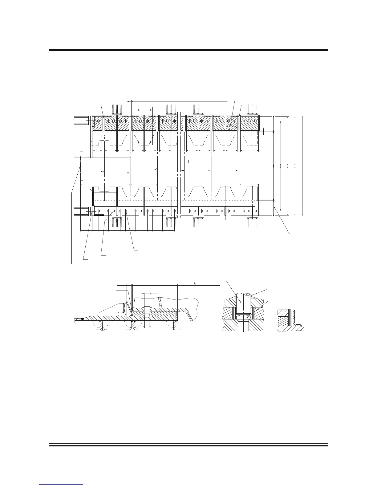
Epoxy Chocks Arrangement
For details of chocks and bolts see special drawings.
For securing of supporting chocks see special
drawing.
This drawing may, subject to the written consent of
the actual engine builder concerned, be used as a
basis for markingoff and drilling the holes for hold-
ing down bolts in the top plates, provided that:
) The engine builder drills the holes for holding
down bolts in the bedplate while observing the
toleranced locations indicated on MAN B&W
drawings for machining the bedplate
2) The shipyard drills the holes for holding down
bolts in the top plates while observing the toler-
anced locations given on the present drawing
3) The holding down bolts are made in accord-
ance with MAN B&W drawings of these bolts.
Fig. 5.12.01: Arrangement of epoxy chocks and holding down bolts
##
""
!FTERæCURINGæOFæEPOXYæCHOCKS
THEæALIGNMENTæSCREWSæAREæTOæBE
LOOSENEDæAæCOUPLEæOFæTURNSæSOæ
ASæTOæBEæCLEARæOFæTHEæTOPæPLATE
æTOæææENGINE
!!
%POXYæWEDGESæTOæBE
CHISELLEDæAFTERæCURING
TOæENABLEæMOUNTINGæOF
SIDEæCHOCKæLINERS
%FFECTIVEæ
ææ#YL
ææ#YL
ææ#YL
ææ#YL
ææ%NGINE
æHOLESæINæTHEæBEDPLATEæANDææHOLESæINæTHEæTOPPLATE
-XæHOLESæPREDRILLEDææINæTHEæBEDPLATEæANDææHOLESæINæTHEæTOPPLATE
"
"
!
!
ææ!FTæ#YL
æææ4HRUST
æBEARING
æMMæTHICKæDAMMINGS
# #
4HEæWIDTHæOFæMACHININGæON
THEæUNDERSIDEæOFæBEDPLATE
)FæMEASURINGæPINSæAREæREQUIREDæWEæRECOMMENDæTHATæTHEYæAREæINSTALLED
ATæTHEæPOSITIONSæMARKEDæBYæ
!LLæHOTæWORKæONæTHEæTANKTOPæMUSTæBEæFINISHEDæBEFOREæTHEæEPOXYæISæCAST
XæOFFææHOLES
%NDæFLANGEæOFæTHRUSTæSHAFT
¢
¢
¢
¢
¢
¢
¢
¢
¢
¢
¢
¢
æMMæFREEæSPACESæFORæSUPPORTINGæWEDGES
¢
¢
!LIGNMENT
SCREW
0LUG
 Loading...


