MAN B&W 8.06
Page 2 of 2
MAN Diesel
MAN B&W S50MCC, S50MEC, S50ME-B8 198 42 581.2
Note:
When calculating the tank heights, allowance has
not been made for the possibility that a quantity of
oil in the lubricating oil system outside the engine
may be returned to the bottom tank, when the
pumps are stopped.
The lubricating oil bottom tank complies with the
rules of the classification societies by operation
under the following conditions:
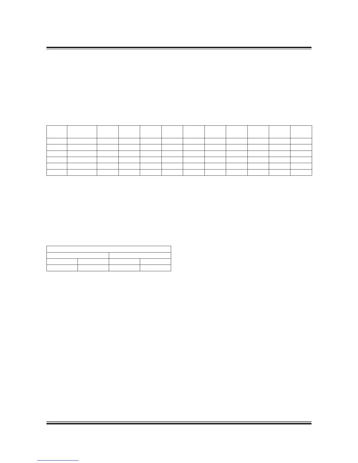
Angle of inclination, degrees
Athwartships Fore and aft
Static Dynamic Static Dynamic
15 22.5 5 7.5
Cylin-
der No.
Drain at
cylinder No.
D0 D1 H0 H1 H2 H3 W L OL Qm
3
4 24 175 375 885 375 75 300 400 4,500 785 7.8
5 25 200 425 925 425 85 300 400 5,250 825 9.6
6 26 200 425 1,005 425 85 300 400 6,750 905 13.6
7 257 225 450 1,035 450 90 300 400 7,500 935 15.6
8 258 250 475 1,085 475 95 400 500 8,250 985 18.0
9 2-5-7-9 250 475 1,115 475 95 400 500 9,750 1,015 22.0
Table 8.06.01b: Lubricating oil tank, with cofferdam
If the system outside the engine is so designed
that an amount of the lubricating oil is drained
back to the tank, when the pumps are stopped,
the height of the bottom tank indicated in Table
8.06.01b has to be increased to include this quan-
tity. If space is limited, however, other solutions
are possible.
Lubricating oil tank operating conditions
 Loading...


