MAN B&W 5.10
Page 2 of 2
MAN Diesel
MAN B&W S50MC-C8
198 60 99-7.0
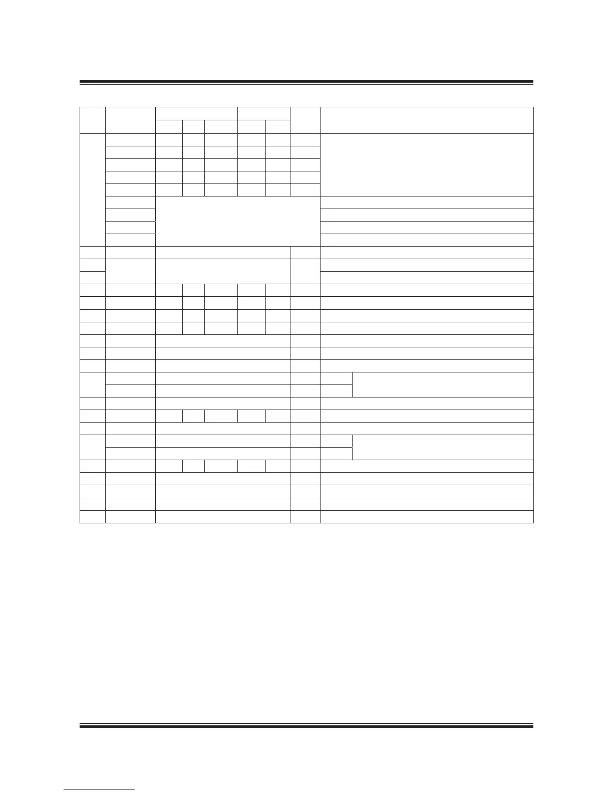
Table 5.10.01: List of counteranges,5-8S50MC-C8. Reference is made to section 5.09 Engine Pipe Connections.
Refe
rence
Cyl. no.
Flange Bolts
DN * Description
Diam. PCD Thickn. Diam. No.
AB
TCA66 20 70 8 M6 4 00
Lubricating oil outlet from MAN Diesel, MHI & ABB
(TPL) turbocharger
TCA77 20 70 8 M6 4 00
TPL73B-CL 85 45 8 M6 4 65
TPL77B 200 60 20 M6 8 80
TPL80B 200 60 20 M6 8 80
MET53MA
Available on request
MET60MA
MET66MA
MET83MA
AC
5-8 Coupling for 6 mm pipe H.J. Lubricating oil inlet to cylinder lubricators
AC
5-8 Coupling for 42 mm pipe
AL-
PHA
Lubricating oil inlet to cylinder lubricators
AU Lubricating oil outlet to service tank
AE 5-8 40 00 8 M6 4 32 Drain from bedplate / cleaning turbocharger
AF 5-8 40 00 8 M6 4 32 Clean fuel to service tank
AG 5-8 40 00 8 M6 4 32 Drain oil from piston rod stufng boxes
AH 5-8 40 00 8 M6 4 32 Fresh cooling water drain
AK 5-8 Coupling for 30 mm pipe Inlet cleaning air cooler
AL 5-8 Coupling for 25 mm pipe Drain from water mist catcher
AM 5-8 Coupling for 25 mm pipe Outlet air cooler to chemical cleaning tank
AN
5-8 Coupling for 30 mm pipe ABB
Water inlet for cleaning of turbocharger
5-8 Coupling for 25 mm pipe MBD
AP 5-8 Coupling for 2 mm pipe Air inlet for dry cleaning of turbocharger
AR 5-8 50 0 8 M6 4 40 Oil vapour disharge
AS 5-8 2 x Hose connection 20 mm Cooling water drain air cooler
AT
5-8 Coupling for 42 mm pipe Steam
Extinguishing of re in scavenge air box
5-8 Coupling for 25 mm pipe CO
2
AV 5-8 85 45 20 M6 4 65 Drain from scavenge air box to closed drain tank
BD 5-8 Coupling for 0 mm pipe Fresh water outlet for heating fuel oil drain pipes
BX 5-8 Coupling for 0 mm pipe Steam inlet for heating fuel oil pipes
BF 5-8 Coupling for 0 mm pipe Steam outlet for heating fuel oil pipes
BV 5-8 Coupling for 20 mm pipe Steam inlet for cleaning of drain scavenge air box
Note: Data for 9 cylinders is available on request.
* DN indicates the nominal diameter of the piping on the engine. For external pipes the diameters should be calculated
according to the uid velocities (see list of capacities) or the recommended pipe sizes in diagrams should be used.
504 63 71-4.0.0
 Loading...


