Interface CAN-2 touch display
152
Read this manual carefully before starting any work!
This is particularly applicable to the chapter “General Safety Instructions”
and the respective safety instructions in the chapters.
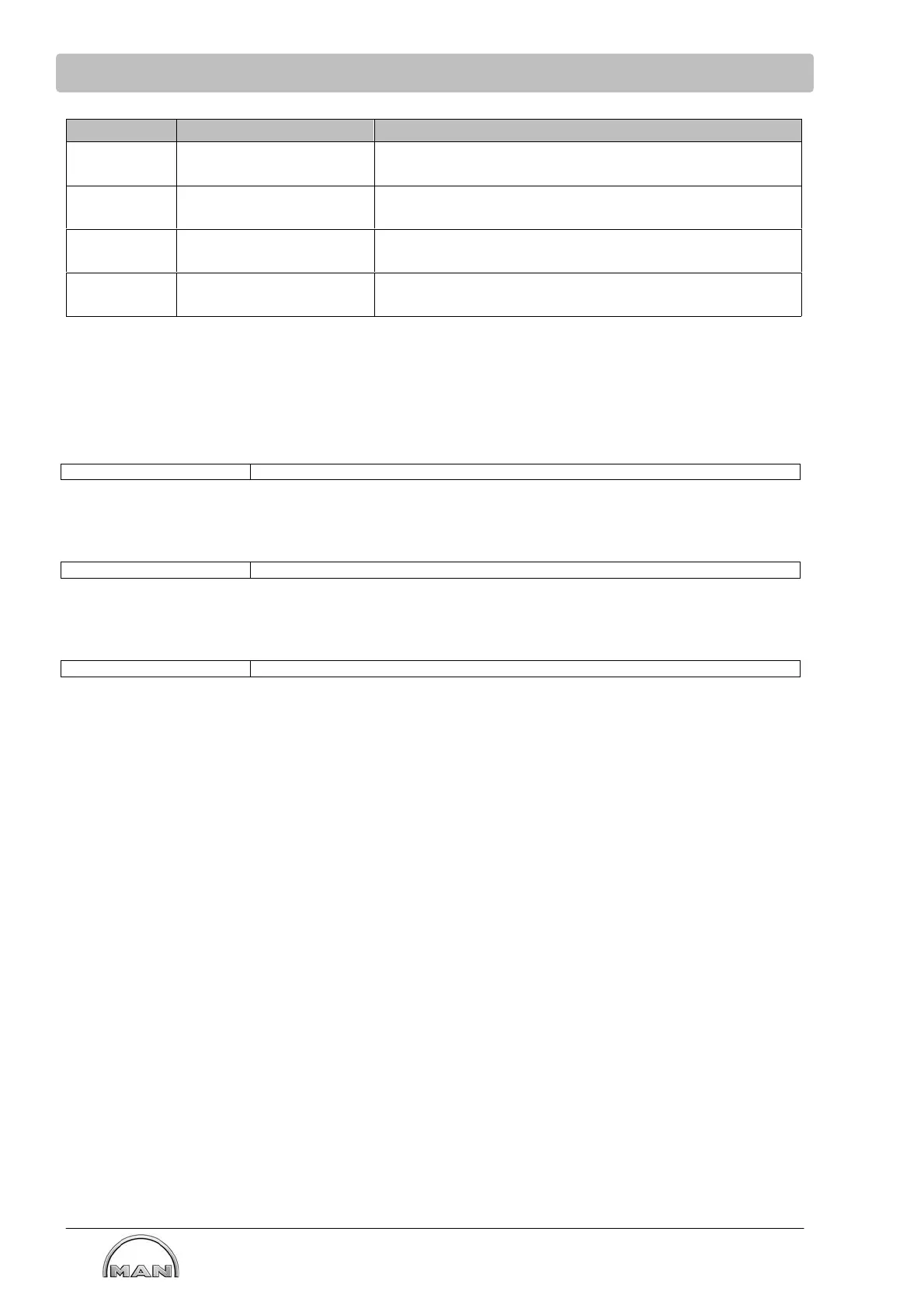
SPN FMI is set to Description
520209
Sensor failure = 2
Warning/Alarm = 14
Inducement Failure Dosing System Error
520210
Sensor failure = 2
Warning/Alarm = 14
Inducement Failure Interrupt of Dosing
520211
Sensor failure = 2
Warning/Alarm = 0
Oil Temperature Axial Bearing
520212
Sensor failure = 2
Warning/Alarm = 1
Gear Lube Oil Pressure
DM1 Single Message 0x1CFECA27
Byte 1: Readiness and Error Lamp Status
Bit 1, 2: Protect Lamp Status (equals Sensor Failure)
00
bin
no Sensor Failure active
01
bin
Sensor Failure active
MAN-specific
Bit 3, 4: Amber Warning Lamp Status (equals Warning)
00
bin
no Warning active
01
bin
Warning active
MAN-specific
Bit 5, 6: Red Stop Lamp Status (equals ALARM)
00
bin
no Alarm active
01
bin
Alarm active
MAN-specific
Bit 7, 8: not used = 11
bin
Byte 2: not used = 0xFF
Byte 3: Bits 1 - 8: SPN (8 least significant bits of SPN (bit 8 most significant))
Byte 4: Bits 1 - 8: SPN (second byte of SPN (bit 8 most significant))
Byte 5: Bits 1 - 5: FMI (Fault Monitoring Identifier, according table above)
00000
bin
Data valid but above normal operational range
00001
bin
Data valid but below normal operational range
00010
bin
Data erratic, intermittent or incorrect
01110
bin
Special instructions - necessity for the service technician to take some action to
complete the specific diagnosis
Bits 6 - 8: SPN (most significant bits of SPN (bit 7 is MSB of SPN))
Byte 6: Bits 1 - 7: Occurrence Counter
set to 0000000
bin
, if no failure is active
set to 0000001
bin
, if a failure is active
Bit 8: CM (SPN conversion method)
set to 0
bin