Drive lever control unit
44
Read this manual carefully before starting any work!
This is particularly applicable to the chapter “General Safety Instructions”
and the respective safety instructions in the chapters.
Connection of the CAN bus cable to a drive lever
NOTICE
Defective wiring of the drive lever control unit and the drive lever leads to malfunctions in data
communication
For this reason:
S Connect the CAN bus as instructed.
The CAN bus cables from the manufacturer Aventics are provided depending on the order.
The drive levers and the drive lever control units MPC are connected with shielded M12 CAN bus cables.
These cables are necessary to prevent the influence of electromagnetic radiation (e.g. cell phones) on the
drive lever control unit.
Adapters are required for connection of the CAN bus cable to the drive lever.
When installing the wiring, ensure that the drive lever CAN bus cables between the drive lever control units
and the associated drive levers are not crossed.
Non-classified system:
The CAN cross-communication between E-box port and starboard engine is effected at the cable conduit
(PG gland).
Classified system:
Cross-communication with the second engine is not available for the E-box with acceptance.
The terminating resistors are to be inserted as shown and activated via DIP switches.
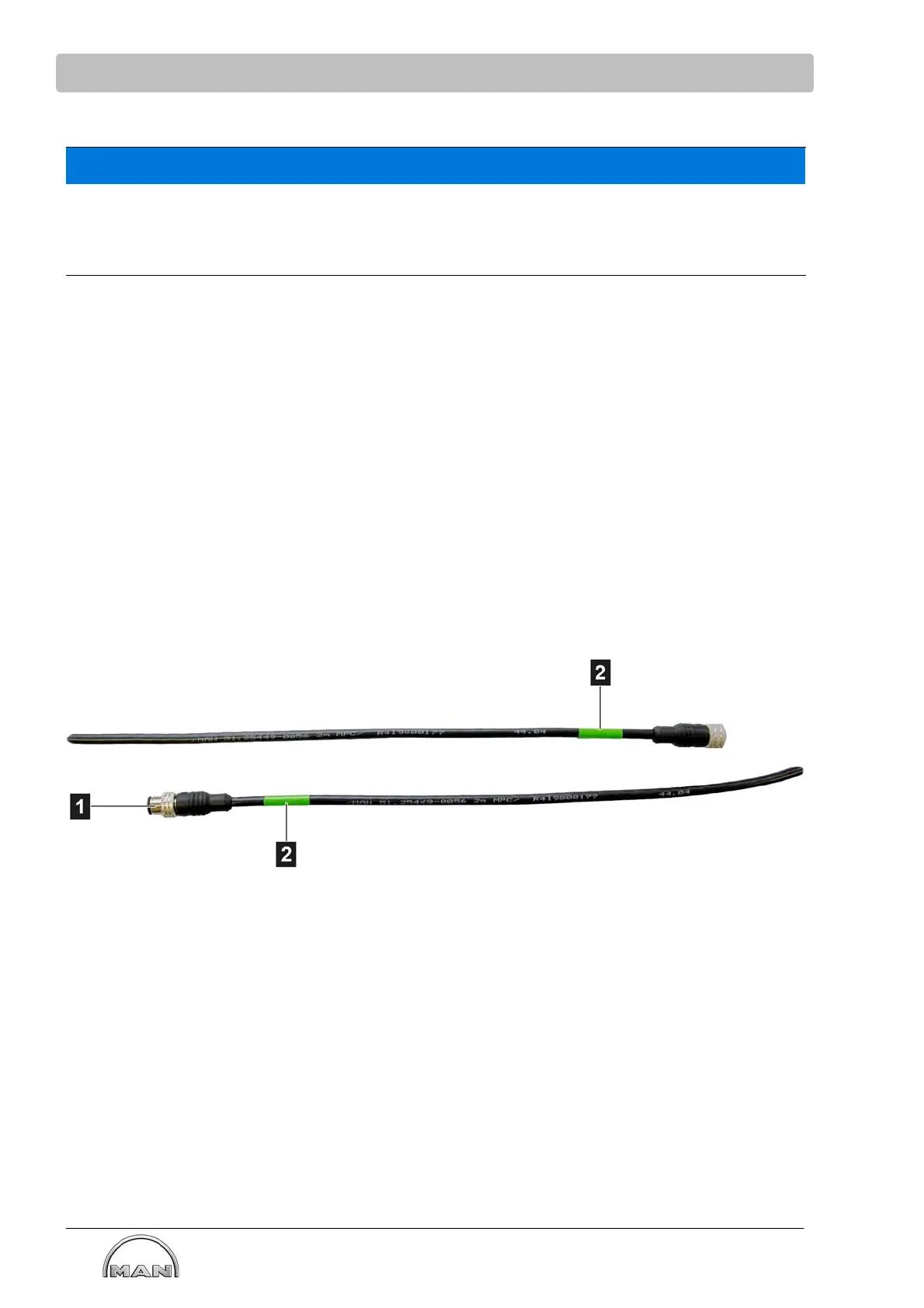
CAN bus cable
CAN BUS connecting cables and terminating resistors
To prevent confusion with other CAN bus cables, pay attention to the metallic guide (1) of the union nuts
and the green marking (2) at the cable ends.