STRUCTURAL CD3340B/YB4411
11-24
Published 04/07/2015 Control # 569-00
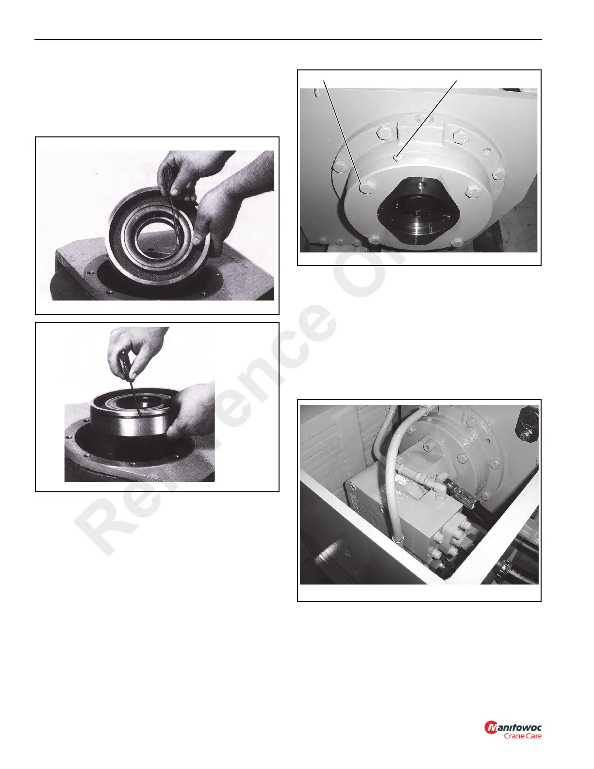
9. Install a new seal (4), O-ring (12) into the bearing carrier
(11). Install bearing (5) into the bearing carrier
(Figure 11-41). Grease the O-ring on the bearing carrier
(Figure 11-42) and install the bearing carrier into the
drum. It must be installed with the O-ring nearest the
motor end.
10. Place the brake section into the hoist bracket
(Figure 11-43). Make sure that the pilot of the brake
section aligns with the bore in the bearing carrier and
that the bolts for the motor are aligned properly. Install
the mounting capscrews and tighten to a torque of 130
to 143 Nm (100 to 110 lb-ft). Also, make sure that the
level and vent plugs (Figure 11-43) in the cover are
properly oriented.
11. Install a new O-ring (17, Figure 11-33) on the face of the
motor and install the motor/brake valve assembly and
connect the hoses.
12. Fill both the gearbox and the brake section with the
proper amount and type of lubricant. See table in
Section 5.
Motor Group
1. Tag the hoses for proper installation and remove them
from the motor and brake valve.
2. Remove the brake valve from the motor. See
Figure 11-44.
3. Remove the cartridge from the brake valve and inspect
the metering hole (Figure 11-45) to make sure it is not
obstructed. Also, check the O-rings to ensure that they
are not cut or flattened. Replace if necessary.
FIGURE 11-43
p0830
Brake
Vent Plug
Reference Only

 Loading...


