GROVE 11-33
CD3340B/YB4411 STRUCTURAL
11
Published 04/07/2015 Control # 569-00
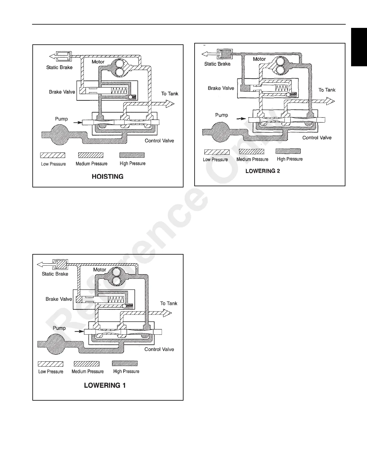
When the control valve is placed in the lowering position, the
spring loaded, pilot operated spool valve remains closed
(Figure 11-69) until sufficient pilot pressure is applied to the
end of the spool valve to shift it against spring pressure;
opening a flow passage (Figure 11-70). After the pilot
operated spool valve cracks open, the pilot pressure
becomes flow-dependent and modulates the spool opening
which controls the lowering speed.
The static brake system has thee operating components
(see Figure 11-67):
1. Spring applied, multiple friction disc static brake
2. Brake clutch assembly
3. Hydraulic piston and cylinder
The static brake is released by the brake valve pilot pressure
at a pressure lower than that required to open the pilot
operated spool valve. This sequence assures that dynamic
braking takes place in the brake valve and that little, if any,
heat is absorbed by the friction brake.
The friction brake is load holding brake only, and has nothing
to do with dynamic braking or rate of descent of a load.
The brake clutch is spline to the primary sun gear shaft
between the motor and the primary sun gear. It will allow this
shaft to turn freely in the direction to raise a load and lock up
to force the brake discs to turn with the shaft in the direction
to lower a load. See Figure 11-71 and 11-72.
The hydraulic cylinder, when pressurized will release the
spring pressure on the brake disc, allowing the brake discs to
turn freely.
Reference Only

 Loading...


