STRUCTURAL CD3340B/YB4411
11-42
Published 04/07/2015 Control # 569-00
rope in. An easy way to check the rotation is to hold the
outer race in one hand, and rotate the inner race.
If the clutch free wheels in the wrong direction,
disassemble the clutch and reverse the inner race. Refer
to “Brake Clutch Service, on page 11-49 for additional
information.
14. If the brake discs are misaligned: preventing the
installation of the clutch, then with a hand pump, apply
750-1000 psi to the brake release port. The brake discs
will move freely with the brake released, permitting
alignment of the discs, brake clutch and input sun gear.
15. Install the hoses and fittings to the brake cylinder
release port (Figure 11-95)
16. Install a new O-ring on the motor pilot then lubricate with
petroleum jelly or gear oil.
NOTICE!
Care must be taken to assure the primary thrust plate
remains properly located in its counter bore when the
motor is installed for the first time, or is being reinstalled
on the hoist. It is possible for the primary thrust plate to
drop out of its counter bore and become wedged
between the planet gears and the planet carrier. If the
hoist is operated with the primary thrust plate wedged
between primary gears and the planet carrier, or with a
thrust washer out of position, severe damage to internal
hoist components could result.
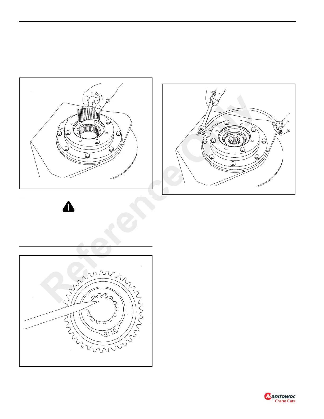
17. Measure the distance from the motor mounting surface
to the inner brake race (Figure 11-96). With all
components properly installed, this distance should be
17.5 mm (11/16 in) to 19.1 mm (3/4 in). If this distance is
less than 14.3 mm (9/16 in), the primary spacer may be
positioned as shown in Figure 11-97 and should be
checked.
WARNING
Be certain the snap ring (Figure 11-94) is seated in the
groove in the spline bore of the inner race. This snap ring
will keep the brake clutch assembly correctly positioned in
the center of the friction brake pack. Binding of the brake
or brake failure may occur if this snap ring is omitted.
Reference Only
 Loading...


