POWER TRAIN TMS700E SERVICE MANUAL
7-38 Published 01-29-2015, Control # 512-01
9. Tighten the bolts in the criss-cross sequence to pull the
clutch into its proper position in the flywheel pilot. You
must start with the lower left-hand bolt.
10. To achieve the final torque, progressively tighten all bolts
61 to 68 Nm (45 to 50 lb-ft).
As the bolts are tightened, the wooden spacers should fall
out. If they do not fall free, remove them. If necessary, lightly
tap on the aligning tool with a mallet to remove it.
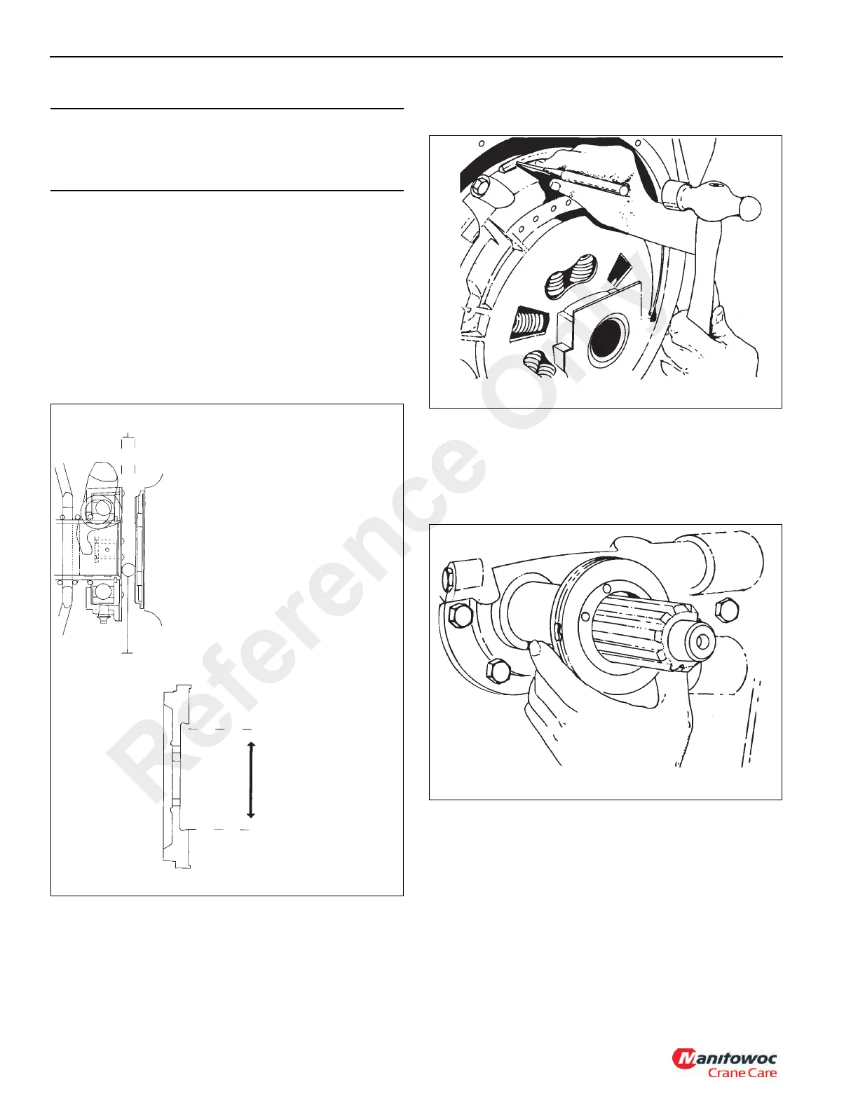
Bearing position should be approximately 9.5 to 15.9 mm
(0.375 to 0.625 in) from the clutch cover (Figure 7-23).
If greater than 15.9 mm (0.625 in) check possible disc to
flywheel bore interference.
11. Check Positive Separators.
Using a 6 mm (0.25 in) diameter flat nose drift, lightly tap
each of the four positive separator pins toward the flywheel.
After tapping, the pins should be flush against the flywheel
(Figure 7-24).
- Remove rust and contamination from input shaft.
- Replace the shaft if any wear is noticed. The clutch
won’t release if the shaft is notched.
- Do not coat the shaft with grease or never seize.
Install discs dry or wipe on a light coat of oil.
If a clutch brake is used, be sure to install it on the input shaft
of the transmission at this time (Figure 7-25).
12. Refer to Manual Transmission on page 7-42, Installation
in this Section, and install the transmission.
Clutch Adjustment Procedure
Remove the inspection plate from the bottom of the clutch
housing and make the following inspections and adjustments
if required.
CAUTION
Failure to tighten the bolts in this manner can cause
permanent damage to the clutch or create an out-of-
balance condition.
MEASURE
BORE SIZE
0.375-0.625 in
9.5-15.9 mm
9.5-15.9 mm
(0.375-0.625 in)
If greater than 15.9 mm (0.625 in), check
flywheel for potential damper interference.
- 8 Springs need 18.4 cm (7.25 in) bore
- 10 Springs need 21.7 cm (8.56 in) bore.
- 7 Springs need 24.8 cm (9.75 in) bore.
- 9 Springs need 24.8 cm (9.75 in) bore.
- Discs could be incorrectly installed.
- Possible over machined flywheel (damper
may hit flywheel bolts).
4863-12
FIGURE 7-23
Reference Only

 Loading...


