Grove Published 01-29-2015, Control # 512-01 7-37
TMS700E SERVICE MANUAL POWER TRAIN
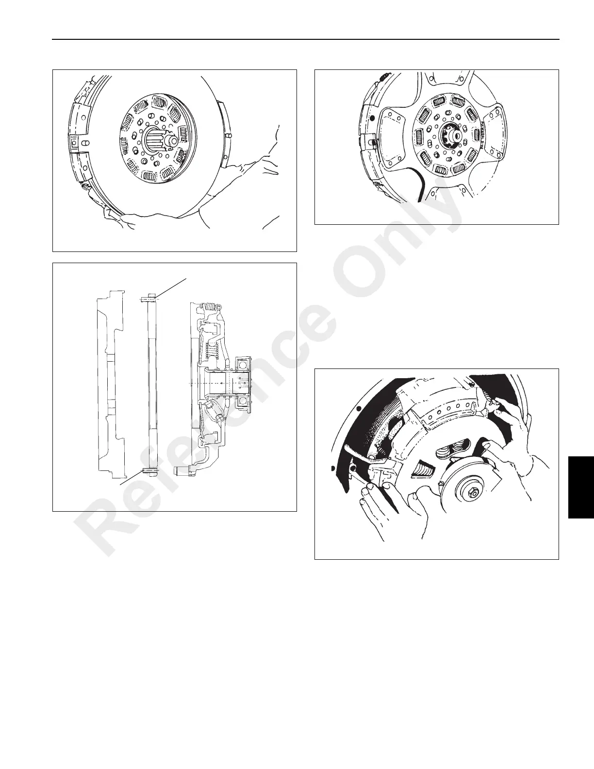
5. Positive separator (roll) pins should be flush on the
clutch side, protruding on flywheel side (Figure 7-20).
6. Install the front disc on the aligning tool with the side
stamped “flywheel” facing the engine (Figure 7-21).
NOTE: It’s imperative that the side stamped “flywheel”
faces the engine and the side stamped “pressure
plate” faces the transmission.
The relative position of the buttons on the front and rear
driven discs is not important.
NOTE: Ensure the adjustment mechanism will be aligned
with the opening in the bell housing of the
transmission.
7. Position the clutch over the guide studs and slide it
forward until contact is made with the flywheel surface.
The clutch assembly weighs approximately 66.5 kg
(146 lb), so a hoist may be required to lift it into place
(Figure 7-22).
8. Start the eight 7/16 inch bolts with lock washers and
tighten them finger tight.
Protruding
Flush
4863-8
FIGURE 7-20
Reference Only

 Loading...


