POWER TRAIN TMS700E SERVICE MANUAL
7-36 Published 01-29-2015, Control # 512-01
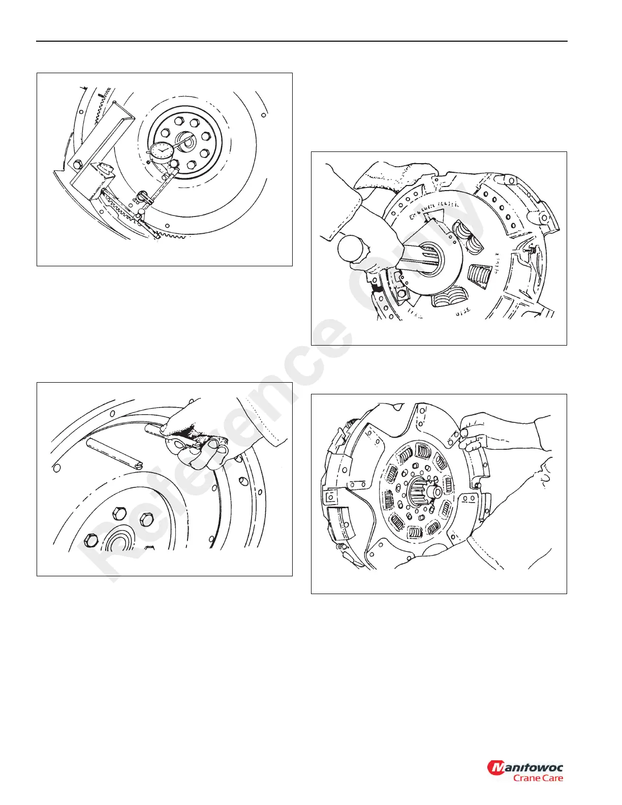
6. Move the gauge finger to contact the pilot bearing bore
surface. Again, rotate the flywheel (Figure 7-15).
The maximum total allowable runout is 0.13 mm (0.005 in). If
these limits are exceeded, the problem must be corrected or
misalignment will cause premature wear to the drive train
components
Installation
1. Insert two 13 cm (5 in) long 7/16 inch - 14 UNC guide
studs into the two upper mounting holes of the flywheel
(Figure 7-16).
2. Verify flywheel cavity.
- 8 Springs need 18.4 cm (7.25 in) bore
- 10 Springs need 21.7 cm (8.56 in) bore.
- 7 Springs need 24.8 cm (9.75 in) bore.
- 9 Springs need 24.8 cm (9.75 in) bore.
Insert the aligning tool through the release bearing sleeve in
the new clutch (Figure 7-17).
3. Put the rear driven disc on the aligning tool with the side
stamped “pressure plate” facing the pressure plate
(Figure 7-18).
4. Place the intermediate plate in the clutch cover and align
the driving lugs of the plate with the slots provided
(Figure 7-19).
Reference Only

 Loading...


