Grove Published 01-29-2015, Control # 512-01 8-27
TMS700E SERVICE MANUAL UNDERCARRIAGE
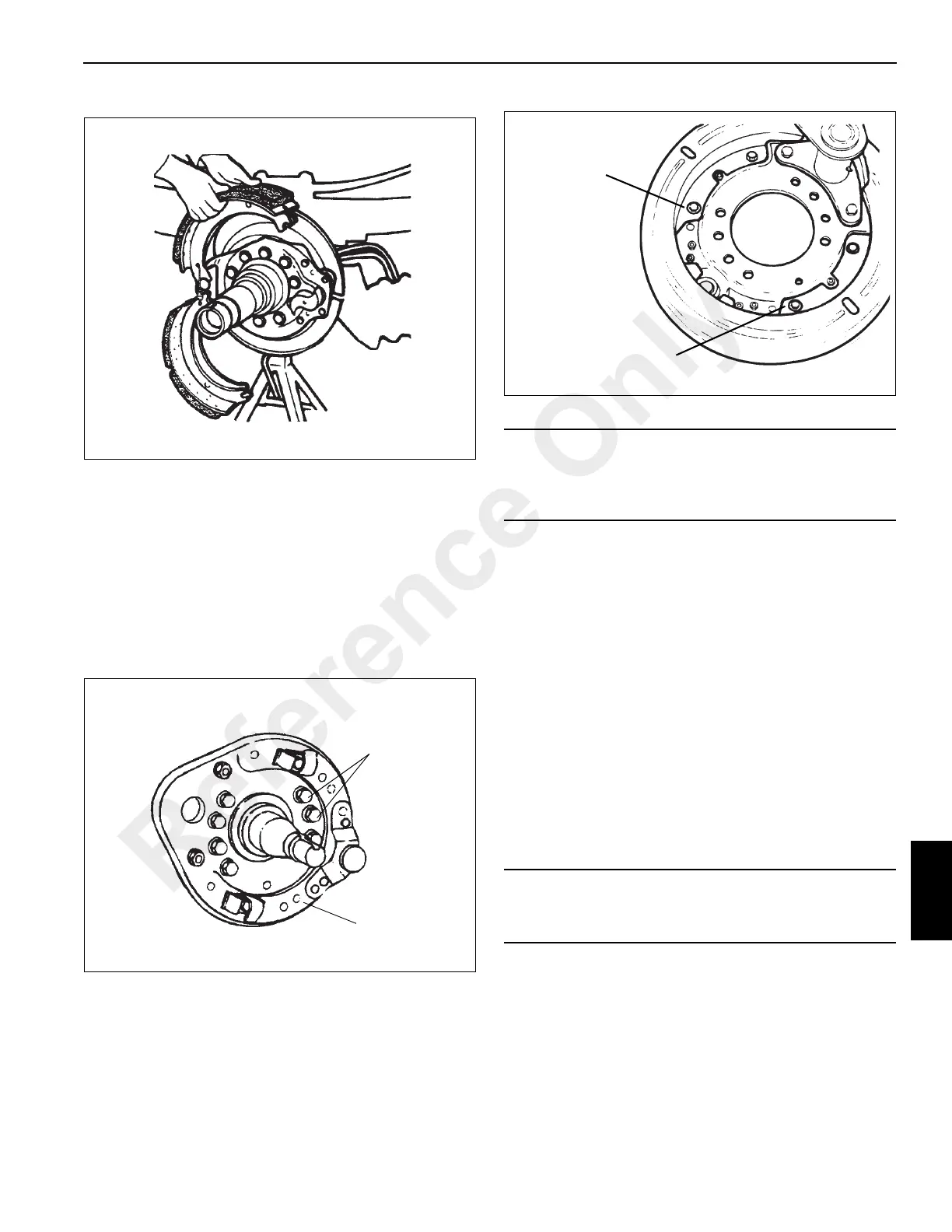
13. Remove the shoes from the axle (see Figure 8-19).
14. Remove the slack adjuster. Refer to Automatic Slack
Adjuster, page 8-30.
15. Remove the camshaft by grasping the camshaft head
and pulling outboard.
16. Remove the bolts attaching the air chamber bracket to
the spider and pull it away from the spider.
17. Remove spider-to-axle attaching nuts and bolts and
remove the spider (see Figure 8-20).
18. Remove screws and retaining clip securing dust shield
to spider and remove dust shield (see Figure 8-21).
19. Clean brake parts as outlined below:
a. Wire brush all parts exposed to mud, road dirt, and
salt, to include the spider, air chamber bracket, dust
shield, and exterior of drum.
b. Following the recommendations at the beginning of
this section, use a vacuum cleaner to remove brake
dust from drums. Wipe interior of drums with a
greaseless solvent to remove any spilled oil.
c. Clean all other brake parts thoroughly with a
suitable shop solvent. Wipe dry with a clean, lint-
free cloth.
Inspection
1. Check drum for cracks, glazing, grooving, run-out and
out-of-round. Cracked drums must be replaced. Drums
which are glazed, grooved, out-of-round, etc., may be
returned to service if they can be reworked without
exceeding the manufacture’s specifications.
2. Inspect the shoes for bent or cracked webs or table,
broken welds, loose rivets, or elongated rivet holes.
Replace shoes if any are found.
3. Check the anchor pin and cam roller contact areas in the
shoe webs for elongation or wear. Replace the shoe if
the diameter of the roller end exceeds 21.33 mm
(0.835 in) or the diameter of the anchor pin end exceeds
35.56 mm (1.4 in).
Remove all
Mounting Bolts
and Nuts
Spider
FIGURE 8-20
CAUTION
Oxidation and dirt on the outside of brake drum acts as an
insulator and may hinder heat dissipation. Remove with a
wire brush.
CAUTION
Do not use drum if it exceeds maximum diameter or run-
out specifications.
Remove all
four screws
Dust Shield
FIGURE 8-21
Reference Only

 Loading...


