UNDERCARRIAGE TMS700E SERVICE MANUAL
8-42 Published 01-29-2015, Control # 512-01
Apply brake lubricant to all parts except the linings and
drums to prevent rust.
Inspect Parts
1. Check the spider for expanded anchor pin holes and
cracks. Replace damaged spiders and anchor pin
bushings.
2. Check the camshaft bracket for broken welds, cracks,
and correct alignment.
3. Check anchor pins for corrosion and wear. Replace
damaged anchor pins.
4. Check brake shoes for rust expanded rivet holes, broken
welds, and correct alignment. Anchor pin holes must not
exceed 26 mm (1.03 in) in diameter. The distance from
the center of the anchor pin hole to the center of the
roller hole must not exceed 327 mm (12.875 in).
5. Check the camshaft for cracks, wear, and corrosion.
Check the cam head, bearing journals, and splines.
6. Check the slack adjuster for the gap between the clevis
and collar. If the gap exceeds 1.5 mm (0.060 in), replace
the clevis. Check the clevis pins and bushing in the slack
adjuster arm. Replace bushing if diameter exceeds
16.6 mm (0.65 in).
7. Rotate the slack adjuster adjusting nut through a 360
degree rotation (about 22 turns of the adjusting nut) with
a torque wrench. Torque must be less than 2.8 Nm
(25 lb-in) for a new or rebuilt slack adjuster.
8. Check the brake drums for cracks, severe heat
checking, heat spotting, scoring, pitting, and distortion.
9. Measure the inside diameter of the drum in several
locations and replace if diameter exceeds
manufacturers specifications.
10. Check dust shields for rust and distortion. Replace as
necessary.
Assemble Brakes
Each time the brakes are relined, the following parts should
also be replaced.
• Springs
• Rollers
• Anchor Pins
• Clevis Pins
• Camshaft Seals
Camshaft Installation
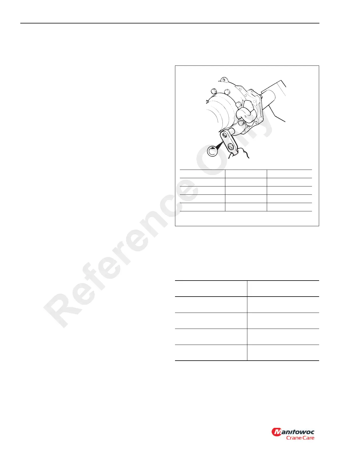
1. Check all spider bolts for the correct torque (see
Figure 8-45).
2. Install new camshaft seals and, if required, bushings in
both the spider and camshaft bracket. Use a seal driver
to install the bushings.
3. If the camshaft bracket was removed, install the gasket
and bracket to the spider. Torque per Table 8-4.
Table 8-4
NOTE: Install both seals with lips toward slack adjuster
(see Figure 8-46).
4. Put the cam head thrust washer on the camshaft. Apply
O-617 - A or B chassis grease to the camshaft bushings
or needle bearings and to the camshaft journals. Install
Size and Grade
Torque
Nm (pounds-foot)
1/2”-13 Grade 8
122 to 163 Nm
(90 to120 lb-ft)
1/2”-13 Grade 5
88 to 136 Nm
(65 to 100 lb-ft)
5/8”-18 Plain Nut
203 to 258 Nm
(150 to 190 lb-ft)
5/8”-18 Lock Nut
176 to 224 Nm
(130 165 lb-ft)
FIGURE 8-45
Bolt Size Nm Pounds-Foot
7/16” - 20 85 - 102 60 - 75
1/2” - 20 115 - 156 85 - 115
9/16” - 18 176 - 224 130 - 165
1/8” - 18 244 - 312 180 - 230
Reference Only

 Loading...


