Grove Published 01-29-2015, Control # 512-01 8-45
TMS700E SERVICE MANUAL UNDERCARRIAGE
4. Rotate the adjusting hex nut clockwise until the slack
adjuster arm hole lines up with the clevis hole (see
Figure 8-52).
5. Install the clevis pin without the cotter pin at this time.
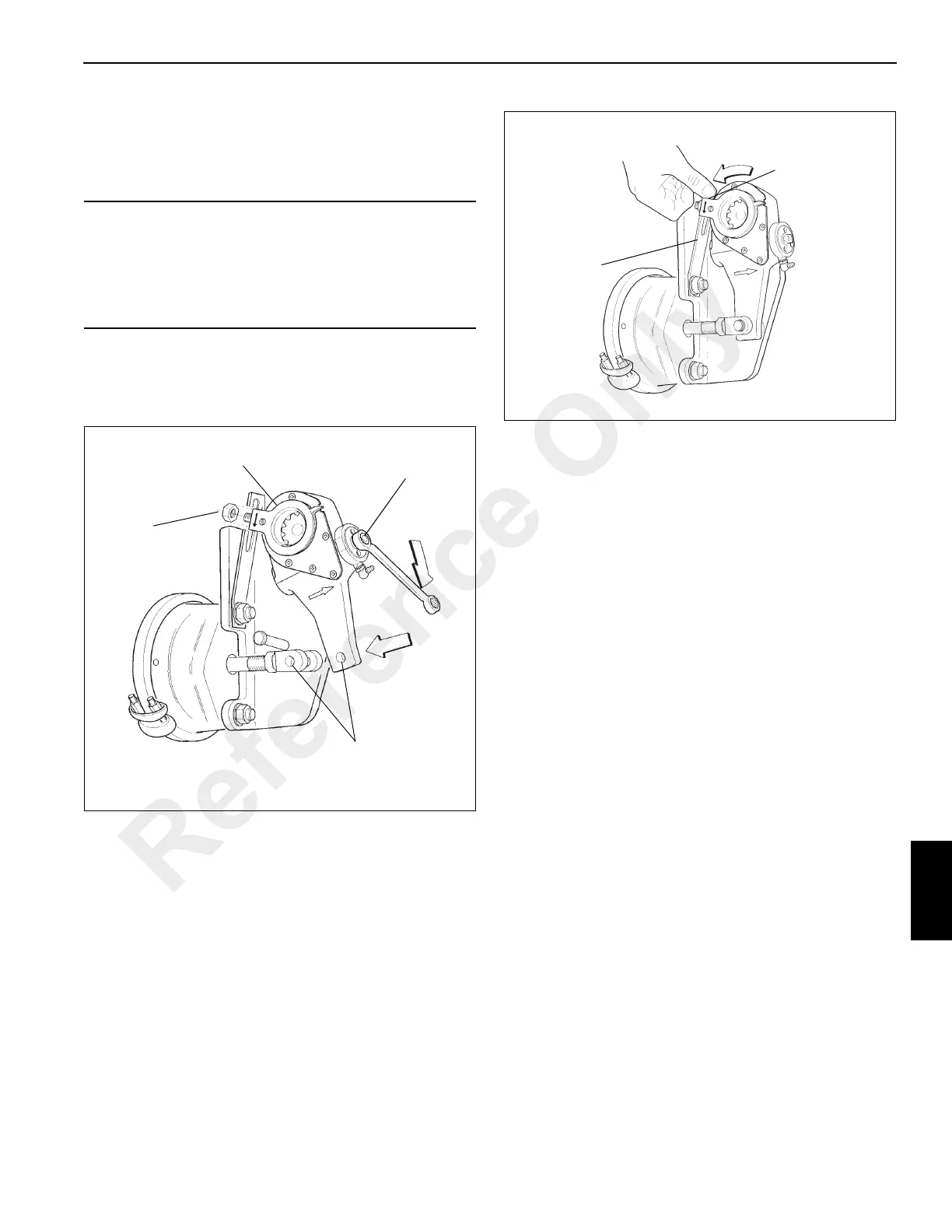
6. Rotate the control arm counterclockwise towards the air
chamber until it comes to a definite internal stop. If
necessary, use a plastic mallet to tap the control arm into
position (see Figure 8-53).
7. Tighten control arm anchor and bracket fastener.
8. Adjust the brakes by turning the adjusting hex clockwise
until the lining contacts the drum. Then rotate the
adjusting hex counterclockwise 1/2 turn. A minimum of
17.6 Nm (13 lb-ft) is necessary to overcome the clutch
and a ratcheting sound will be heard.
9. With the brakes released, verify that the installation
indicator is within the slot. Remove the clevis pin. The
clevis hole and adjuster hole should remain in
alignment. If the air chamber clevis pulls into the air
chamber, repeat the installation procedure.
10. Install the clevis pin and cotter pin.
CAUTION
Excessive positioning force may damage control arm.
Most adjusters will be equipped with an installation
indicator which must fall within the slot for proper
installation. Incorrect control arm position can cause tight
or dragging brakes.
Install
Loosely
Control
Arm
Adjusting
Nut
Adjust Until
Holes Align
FIGURE 8-52
Rotate the Control
Arm Until it Stops
Mounting
Bracket
FIGURE 8-53
Reference Only

 Loading...


