UNDERCARRIAGE TMS700E SERVICE MANUAL
8-46 Published 01-29-2015, Control # 512-01
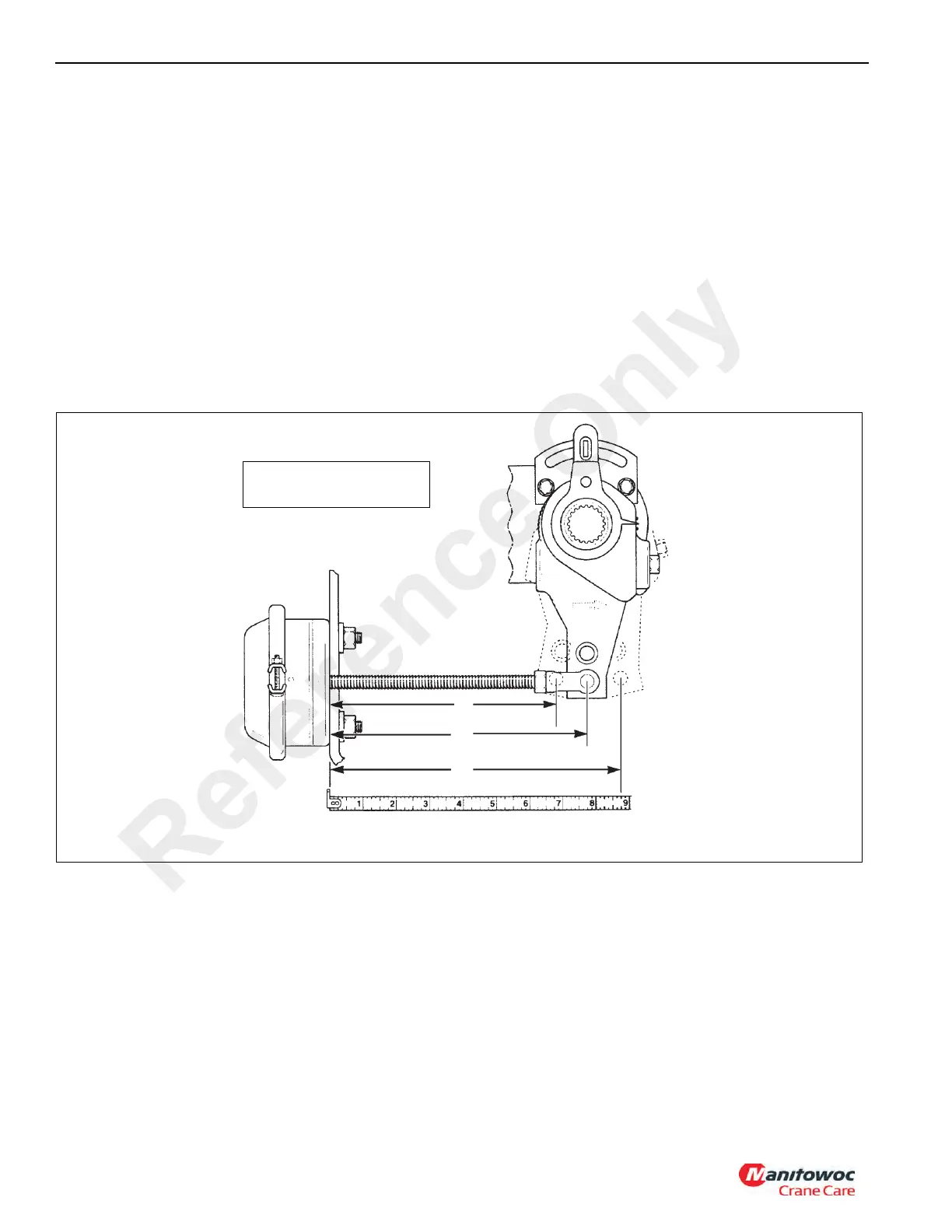
Brake Adjustment
NOTE: See Figure 8-54 for adjustment procedure.
1. Apply the brakes so that the air chamber is fully
retracted. Measure from the face of the air chamber to
the centerline of the clevis pin. Record the measurement
as dimension ‘A’.
2. Pry the slack adjuster so that the brake shoes are in
contact with the drum.
3. Measure between the face of the air chamber and the
centerline of the clevis pin. Record this measurement as
dimension ‘B’.
4. Subtract dimension ‘A’ from ‘B’ to find the free stroke
distance. The minimum free stroke is 9.525 mm
(0.375 in).
5. Spin the wheel by hand to check for drag. Tap the drum
lightly with a hammer and listen for a sharp ringing
sound. If drag is noted, back off the slack adjuster and
recheck free stroke.
6. Apply and hold brakes (5.51 to 6.20 bar (80 to 90 psi)).
7. Measure the distance between the face of the air
chamber and clevis pin centerline. Record as dimension
‘C’.
8. Subtract dimension ‘A’ from dimension ‘C’. The
difference is the applied stroke. Maximum applied stroke
is 5.08 cm (2 in).
9. If the applied stroke is equal to or exceeds the
maximum, adjust the brakes. No adjustment is
necessary if stroke is less than the maximum.
A
B
C
Free Stroke = B minus A
Applied Stroke = C Minus A
FIGURE 8-54
(Fully Retracted)
(Drum Contact Using a Lever)
(551-620 kPa (80-90 psi) Application)
Reference Only

 Loading...


