Grove Published 01-29-2015, Control # 512-01 2-59
TMS700E SERVICE MANUAL HYDRAULIC SYSTEM
1. If removed, install the holding valve. Refer to Holding
Valves, page 2-41 in this section.
.
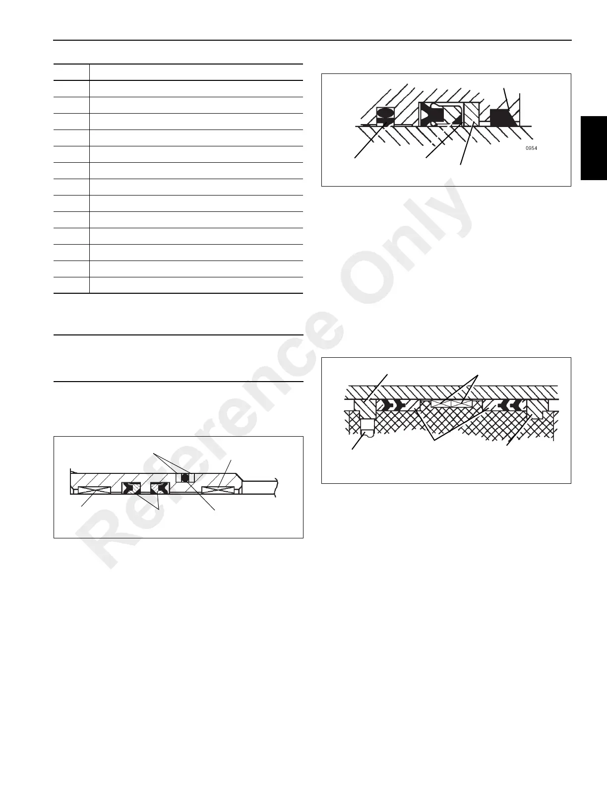
2. Install the O-ring and backup rings on the outside of the
seal retainer and the deep Z rod seals and wear rings in
the inside of the seal retainer (Figure 2-43).
3. Slide the seal retainer onto the inner rod.
4. Install the guide lock ring onto the inner rod and slide the
inner rod and seal retainer into the outer rod.
5. Install the wiper ring, backup ring, deep Z rod seal, buffer
seal assembly, and wear rings into the inside of the
cylinder head (Figure 2-44).
6. Slide the spacer and head onto the outer rod.
7. Install the O-rings and backup rings in the inside of the
piston.
NOTE: Use a new setscrew.
8. Screw the piston onto the outer rod and secure with a
new setscrew.
9. Install the guide lock rings, hydrolock seal assemblies,
and wear rings to the outside of the piston (Figure 2-45).
10. Install the wear rings on the outside of the spacer.
11. Install the O-ring and backup ring on the outside of the
cylinder head.
12. Install the backup ring and O-ring on the outside of the
inner rod end.
13. Clean all oil from the threads of the cylinder head and
apply Loctite #290 to the threads.
14. Slide the rod assembly into the cylinder barrel and screw
the cylinder head into the barrel.
15. Coat the threads of the bolts with Loctite #290. Install the
rod end plate and bolt the plate to the inner rod end with
the bolts and washer. Torque the bolts 195 - 211 Nm
(144 - 156 lb-ft).
16. Bolt the rod retaining plate to the cylinder barrel with the
three 7/16 in. bolts and washers. Torque the bolts 65 - 70
Nm (48 - 52 lb-ft).
23 Piston Hydrolock Seal Assembly
24 Piston Wear Ring
25 Backup Ring
26 Low Temperature O-ring
27 Rod End (Inner Rod)
28 Rod Retaining Plate (Inner Rod)
29 Piston
30 Cylinder Head
31 Spacer
32 Seal Retainer
33 Flatwasher
34 Flatwasher
35 Holding Valve
CAUTION
Do not scratch the grooved and gland surfaces or
damage the seals and O-rings.
Item Description
Backup Rings
Wear Ring
O-Ring
Deep Z Seals
Wear Ring
FIGURE 2-43
Wiper
Deep Z
Buffer
Back-Up
FIGURE 2-44
Set Screw
Guide Lock Ring
Hydro Lock
Seals
Wear Rings
Guide Lock Ring
FIGURE 2-45
Reference Only

 Loading...


