HYDRAULIC SYSTEM TMS700E SERVICE MANUAL
2-62 Published 01-29-2015, Control # 512-01
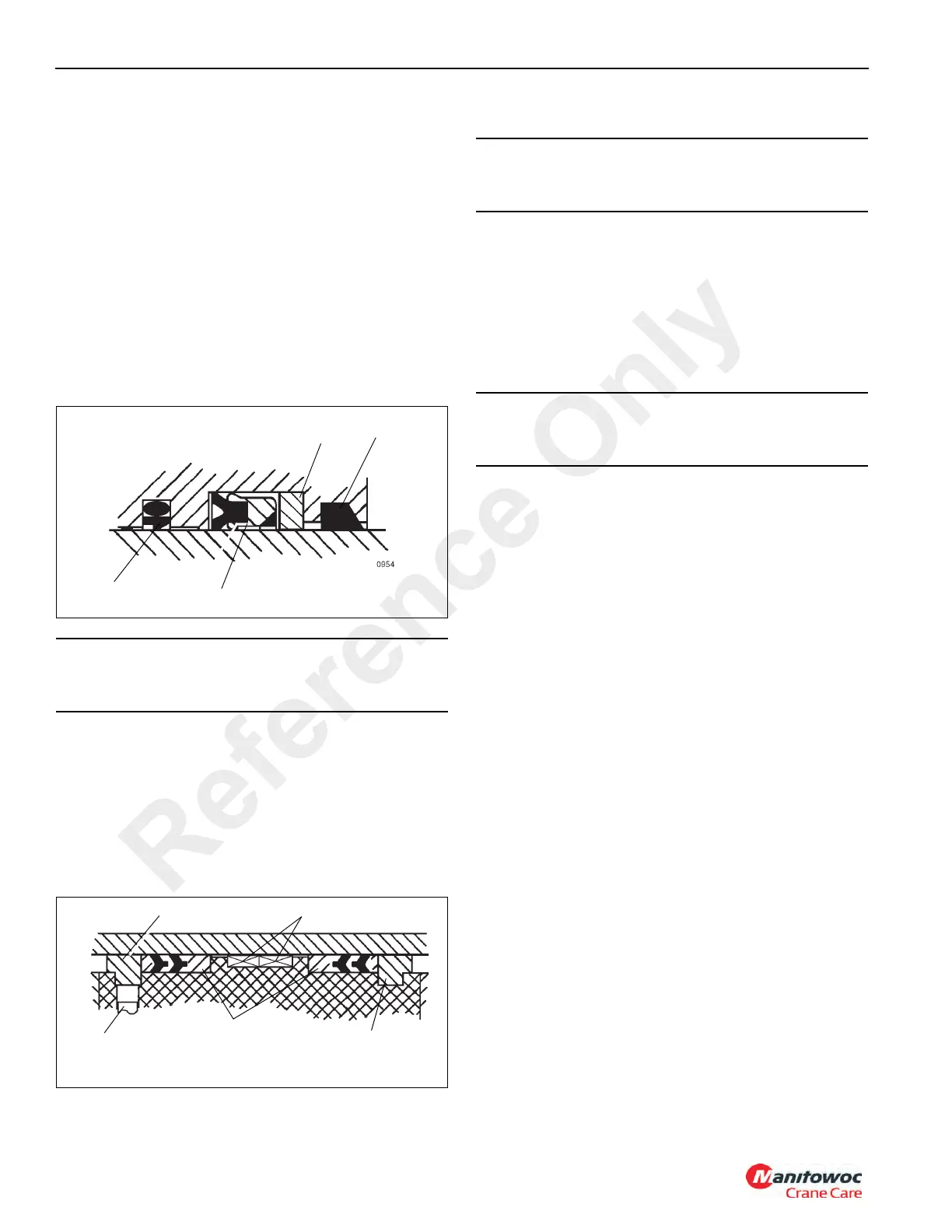
NOTE: When installing seals in step 2 through 4,
(Figure 2-47).
2. Install the wiper ring and wear rings on the inside of the
cylinder head.
3. Install the buffer seal assembly and neutron backup ring
on the inside of the cylinder head.
4. Install the deep Z rod seal inside the head. Make sure
the seals are properly assembled and installed in the
correct direction.
5. Install the low temperature O-ring and backup rings onto
the outside of the head.
6. Install the cylinder head onto the cylinder rod.
7. Install the spacer onto the cylinder rod.
8. Install the low temperature O-ring and backup rings into
the inside of the piston.
NOTE: Use a new setscrew.
9. Screw the piston onto cylinder rod and secure with a
new setscrew.
10. Install the guide lock rings, hydrolock seals and wear
rings onto the outside of the piston (Figure 2-42).
11. Install the wear rings on the outside of the spacer.
12. Clean all oil from the threads of the cylinder head and
apply Loctite #290 to the threads.
13. Lubricate the piston seals and cylinder head O-ring with
clean hydraulic oil and install the rod assembly into the
cylinder barrel with a slight twisting motion.
14. Using a chain wrench, secure the cylinder head to the
cylinder barrel.
15. Pressurize and cycle the cylinder with hydraulic oil
pressure. Test the cylinder at 362 bar (5250 psi). Check
for proper operation and any leakage. Make repairs as
needed.
Bleeding Procedure
This procedure will specify procedures for bleeding the air
from the retract side of the cylinders. There are (2) different
scenarios for bleeding air from these cylinders.
• A cylinder on a test bench.
• A cylinder installed on crane.
Cylinder on Test Bench
1. Install all plugs/valves, extend and retract hoses, etc. as
normal.
2. Attach EMA type hose assembly (p/n 80044628) to
retract bleeder fitting and route to hydraulic tank or drain
tray.
3. Apply retract pressure to cylinder, allowing cylinder to fill
up under atmospheric conditions (no pressure buildup
on retract side). Air will push out through bleeder during
this step.
4. Continue to fill retract side until hydraulic oil starts to
come out of bleeder hose.
5. Stop the retract function, and remove the bleeder hose.
6. Finish testing cylinder as normal.
CAUTION
Improper seal installation could cause faulty cylinder
operation.
Wiper Ring
Deep Z Rod Seal
Buffer Seal
Backup Ring
FIGURE 2-47
Set Screw
Guide Lock Ring
Hydro Lock
Seals
Wear Rings
Guide Lock Ring
FIGURE 2-48
CAUTION
Do not scratch the grooved and gland surfaces or
damage the seals and O-rings.
CAUTION
Do not use air pressure to cycle the cylinder. Use only
controlled hydraulic pressure.
Reference Only

 Loading...


