Manitowoc Published 08-06-19, Control # 237-09_v2 4-3
MLC165-1 OPERATOR MANUAL SETUP AND INSTALLATION
HOSE AND CABLE CLEANLINESS
To prevent dirt from entering the hydraulic systems or from
damaging the electric connectors:
• Thoroughly clean the hydraulic fittings and the electric
connectors before connecting them.
• Thoroughly clean the dust caps before attaching them to
hoses, tubes, or cables.
• Do not drag the hydraulic hose fittings, the hydraulic
hoses, the electric cable connectors, or the electric
cables on the ground.
• Apply a light coat of silicone lubricant to the threads of all
dust caps, couplers, and connectors to help in
preventing the threads from seizing.
CONNECTING/DISCONNECTING
HYDRAULIC HOSES AND ELECTRIC
CABLES
Always STOP ENGINE before performing the following steps
during crane assembly and disassembly:
• Connecting and disconnecting hydraulic lines. It will be
easier to connect and disconnect the couplers when
there is no pressure in the system.
• Connecting and disconnecting electric cables. The
potential for operating faults or damage to the electric
components exists if the engine is not stopped.
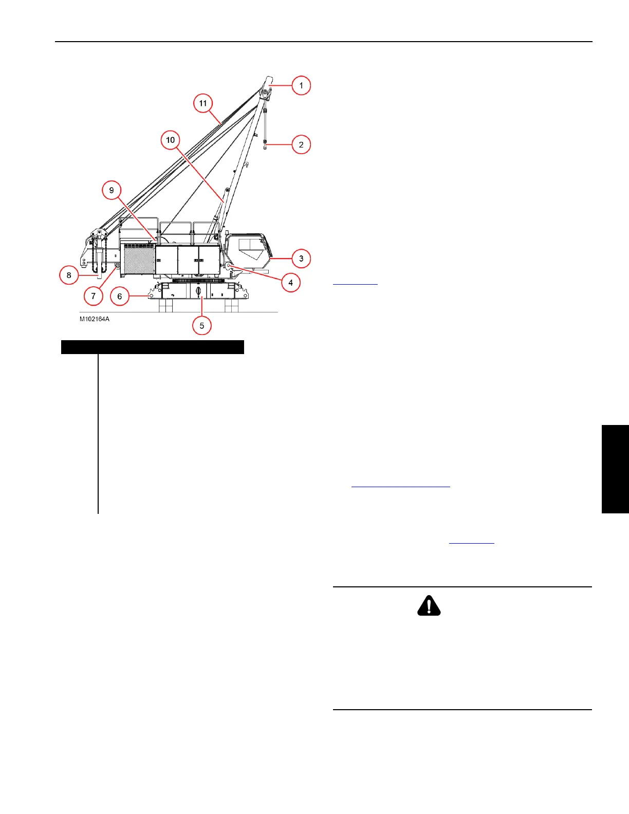
SELF-ASSEMBLY COMPONENTS
The crane is equipped with the following hydraulically
actuated assembly/disassembly components (see
Figure 4-1
):
• Boom hinge pins (4) for connecting the boom butt to the
rotating bed.
• Crawler pins (6) for connecting and disconnecting the
crawlers to and from the carbody.
• Inner counterweight pins (7) for connecting and
disconnecting the counterweight to and from the rotating
bed.
• Counterweight cylinders (8) for installing and removing
the crane counterweight.
• Mast-assist arms (10) for raising the mast to the
operating position and lowering it to the transport
position.
• Controls for operating the above components (see
Figure 4-2 on page 4-4
).
LOAD SENSING PINS
At the crane owner’s discretion for duty-cycle operation only,
the load sensing pins (12, Figure 4-1
) can be replaced with
the mast-to-boom link pins located in the parts box. See the
RCL/RCI Operation Manual for details.
Item Description (Qty)
1Mast
2 Mast-to-Boom Links
3Operator Cab
4 Boom Hinge Pin (2)
5 Carbody
6 Crawler Pin (4)
7 Inner Counterweight Pin (2)
8 Counterweight Cylinder (2)
9 Boom Hoist
10 Mast Assist Arm
11 Boom Hoist Wire Rope
12 Load Sensing Pin (2)
Figure 4-1
WARNING
Tipping/Structural Damage Hazard!
To prevent tipping or structural damage:
• The load sensing pins must be installed for all
liftcrane operations AND
• the proper liftcrane capacity chart must be selected in
the RCL/RCI display.

 Loading...


