SETUP AND INSTALLATION MLC165-1 OPERATOR MANUAL
4-22
Published 08-06-19, Control # 237-09_v2
Install Crawlers – Preliminary Steps
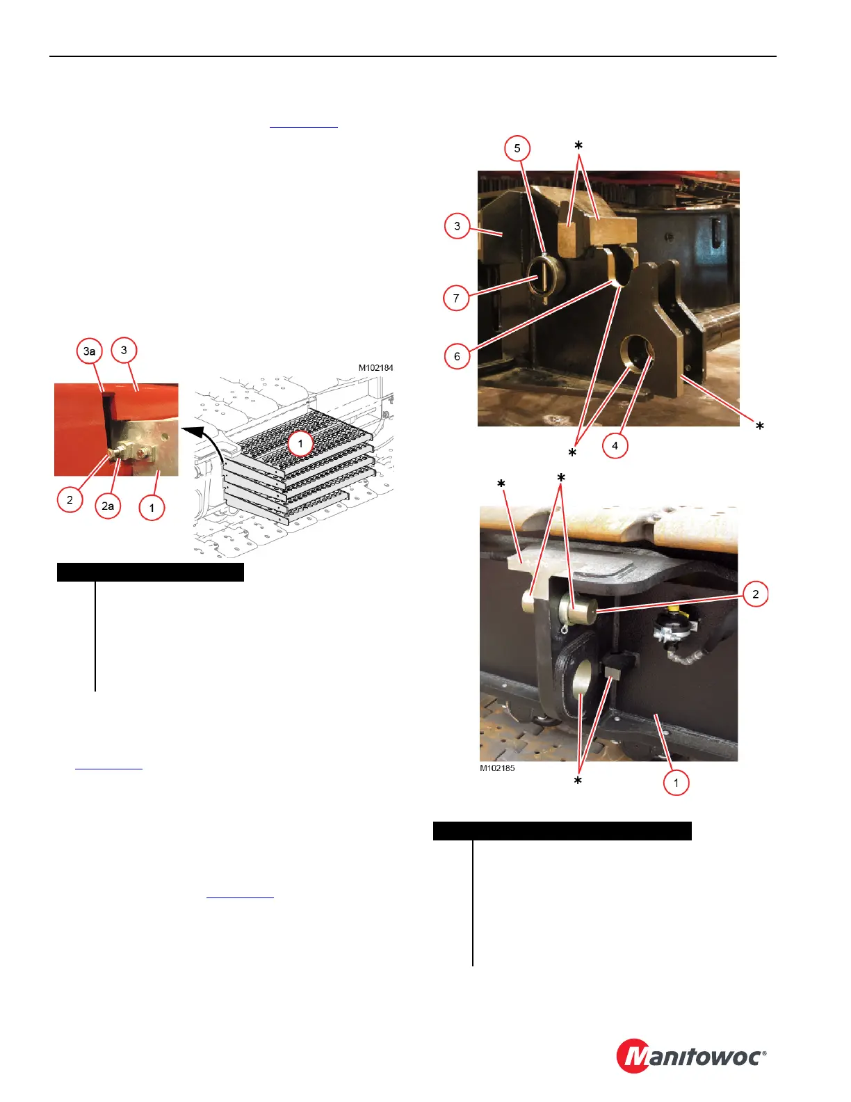
1. Remove the platform sections (1, Figure 4-16) from their
storage position on each crawler and put the sections in
a safe place until the crawlers have been installed:
a. Loosen the lock nut (2a) and the retaining screw (2).
b. Slide and lift the top section (1) out of the slots (3a)
in the frame (3).
Each section weighs approximately 17 lb (8 kg).
c. Repeat the steps for the remaining sections.
The left crawler holds the five left side platforms.
The right crawler holds the four right side platforms.
2. Thoroughly clean and apply Never-Seez
®
or equivalent
anti-seizing compound to all machined surfaces on the
carbody and the crawlers — surfaces marked
in
Figure 4-17.
If this step is not performed, excessive friction will occur
in the closely machined mating surfaces between the
crawlers and the carbody. The result will be loud noises
coming from the lowerworks when turning (cutting) the
crawlers or swinging the upperworks over the corner of
the crawlers.
3. Remove the collar (5, Figure 4-17
) from all four crawler
pins (4).
4. Temporarily store the collars (5) on the storage lugs (7).
5. Start the engine.
6. Using the carbody controls, disengage all four crawler
pins (4).
Figure 4-16
Item Description
1 Platform Sections
2 Retaining Screw
2a Lock Nut
3Frame
3a Slot
*
Machined Surfaces
Figure 4-17
Item Description
1Crawler
2 Alignment Pin
3 Carbody
4Crawler Pin
5 Collar with Pin and Safety Pins
6 Alignment Saddles
7 Storage Lug