Manitowoc Published 08-06-19, Control # 237-09_v2 4-39
MLC165-1 OPERATOR MANUAL SETUP AND INSTALLATION
See Figure 4-32 for the remaining steps.
10. Pin the shackles (2, View D) to the lifting links (7).
Using the switches on the remote control, extend and
retract the counterweight-handling cylinders (8) as
needed to align the shackles with the lifting links.
11. Make sure the inner connecting pins (5) are fully
disengaged.
12. Using the switches on the remote control, extend the
counterweight-handling cylinders (8, View F) to lift the
crane counterweight to its working position. Keep the
counterweight tray (6) as level as possible from
side-to-side as it rises.
13. Stop when the alignment lugs (9, Views F and G) bottom
out against the stop pins (10) and the inner connecting
holes are aligned.
14. Using the switch on the remote control, engage the inner
counterweight pins (5, View E).
15. Install the outer counterweight pins (4, View G).
16. Using the switch on the remote control, fully retract the
counterweight-handling cylinders.
17. The chains and shackles can remain connected to the
lifting links (View G) for crane operation.
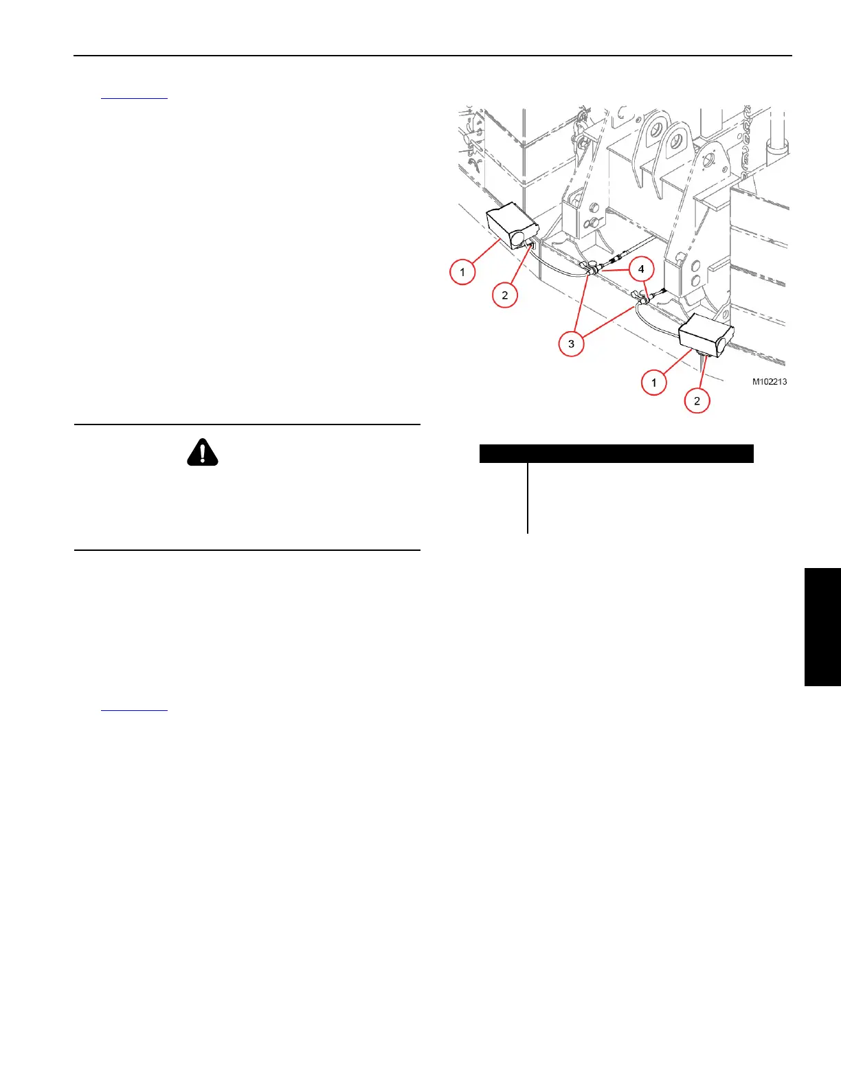
Install Counterweight Work Lights
See Figure 4-33 for the following procedure.
If equipped with optional work lights, install them on the
crane counterweight as follows:
1. Stop the engine.
2. Remove the work lights (1) from storage.
3. Securely fasten the work lights (1) to the counterweight
tray with the cap screws and lock washers (2).
4. Connect the electric cables (3) to the receptacles (4) on
the rear of the counterweight tray.
5. Connect the electric cables from the rotating bed to the
receptacles (4) on the front of the counterweight tray.
6. Loosen the cap screws and nuts and adjust the position
of the lights left-to-right and up-and-down as needed.
7. Securely tighten the cap screws and nuts.
WARNING
Burn Hazard!
Do not climb onto the counterweight tray for any reason
while the counterweight is in the working position.
The exhaust pipe can burn and cause serious injury.
Item Description
1 Work Light (2)
2 Cap Screw and Lock Washer (4)
3 Electric Cable (2)
4 Receptacle (4)
Figure 4-33