Manitowoc Published 08-06-19, Control # 237-09_v2 4-63
MLC165-1 OPERATOR MANUAL SETUP AND INSTALLATION
Lower Boom Stops
See Figure 4-49.
1. Using a basket hitch, attach a synthetic lifting sling from
the assist crane to either boom stop (6, View B) at the
approximate location shown.
2. Hoist just enough to support the boom stop.
3. Remove the pins (7, View D) from the working lugs (10).
4. Lower the boom stop until the strut (9) can be pinned in
the shipping position.
5. Using pin (7, View D), pin the strut (9) to the storage lugs
(8).
6. Disconnect the lifting sling.
7. Repeat the steps for the other boom stop.
Lower Boom Butt Wire Rope Guide
See Figure 4-49.
1. Attach a lifting sling from the hook of the assist crane to
the lifting lugs (3, View B) on the wire rope guide (1).
2. Hoist just enough to support the wire rope guide (1).
3. Remove the pins (2, View A) from the lugs on the boom
butt.
4. Rotate the wire rope guide to the shipping position (View
C).
5. Store the pins (2, View A) in the lugs on the boom butt.
6. Remove the pin (4, View C), rotate the link (5) to the
shipping position, and pin the link (5) to the wire rope
guide (1) with pin (4).
7. Disconnect the lifting sling from the wire rope guide.
Lift Boom Butt onto Trailer
Reverse the step under the topic Remove Boom Butt from
Trailer on page 4-40.
See Shipping Crane Components on page 4-53
.
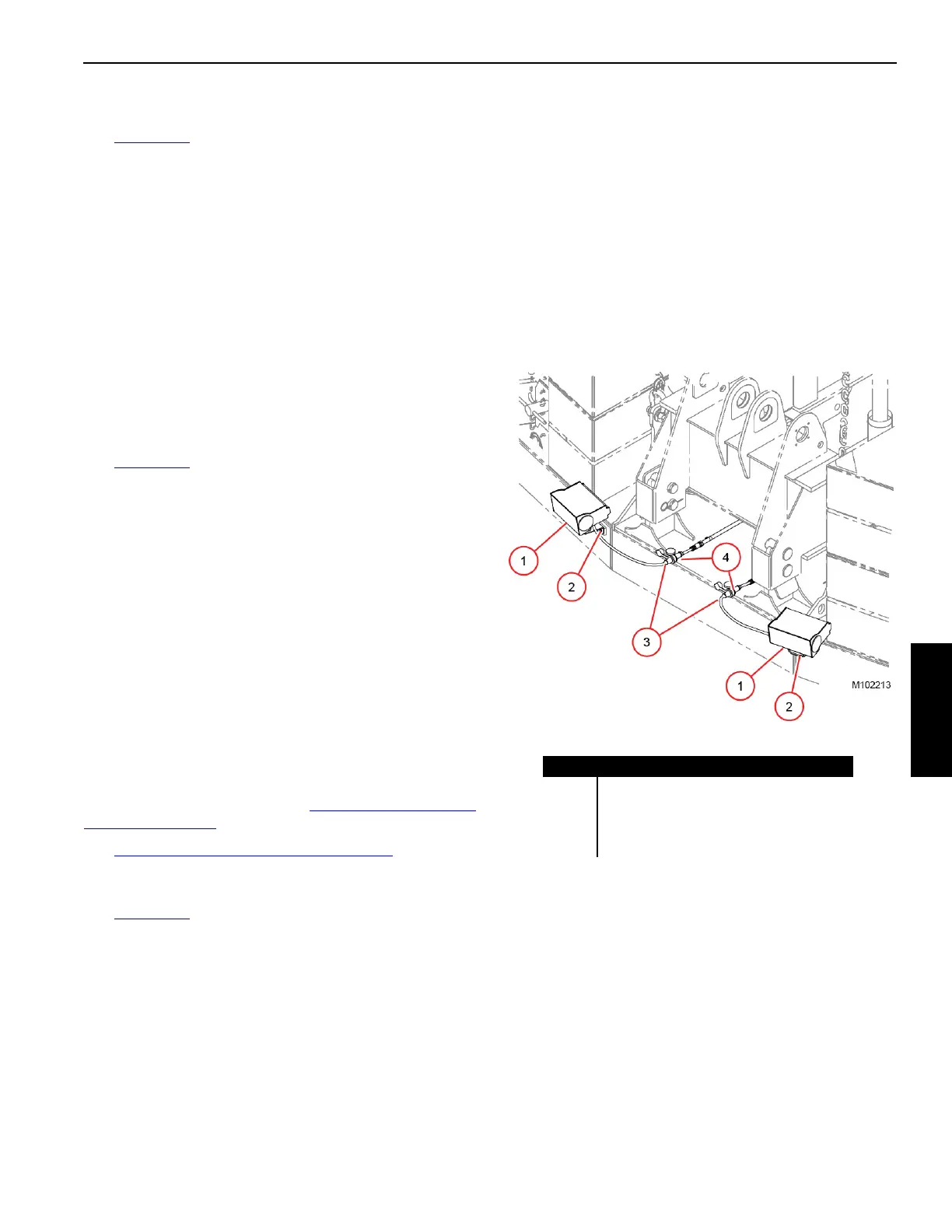
Store Counterweight Work Lights
See Figure 4-50 for the following procedure.
If equipped with optional work lights, store them as follows:
1. Stop the engine.
2. Disconnect the electric cables from the rotating bed at
the receptacles (4) on the front of the counterweight tray.
3. Disconnect the electric cables (3) from the lights at the
receptacles (4) on the rear of the counterweight tray.
4. Remove the cap screws and lock washers (2) securing
the lights to the tray.
5. Remove the work lights (1) and store them.
6. Reinstall the cap screws and lock washers (2) in the
camera mounting holes.
Item Description
1 Work Light (2)
2 Cap Screw and Lock Washer (4)
3 Electric Cable (2)
4 Receptacle (4)
Figure 4-50

 Loading...


