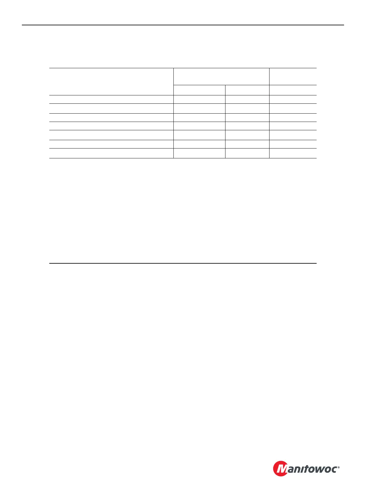
Limit
Limit Bypass Switch
External
Bypass Switch
1
Non-CE
CE
2
CE
2
Boom Max Up No No No
Block Up (each load line) Yes
Yes
3
No
Minimum Bail (each drum) Yes No No
Mast too Far Forward (see Section 4) No No No
Control Handle Faults
Yes
5, 6
Yes
5, 6
Yes
5, 6
Swing Limiter No No No
Rated Capacity Indicator/Limiter Yes
Yes
3, 4
Yes
1
Cranes meeting CE requirements are equipped with this switch located outside the operator cab. See
the MLC165-1 RCL/RCI Manual.
2
CE = Cranes that comply with European requirements. Cranes meeting European requirements are
equipped with an RCL/RCI External Override Switch located outside the operator cab (see the
MLC165-1 RCL/RCI Manual).
3
Only if the boom is below an allowable angle given in the capacity chart (while raising or lowering the
boom from or to the ground level).
4
Rated capacity bypassed up to 110%. The speed of the crane functions is limited to 25% of their
maximum speed for movements that increase load.
5
The alarm will sound.
6
Not bypassable when crane is in setup mode and boom hoist is being operated.
For luffing jib limits and faults, see the MLC165 Luffing Jib Operator Manual.