SETUP AND INSTALLATION MLC165-1 OPERATOR MANUAL
4-100
Published 08-06-19, Control # 237-09_v2
.
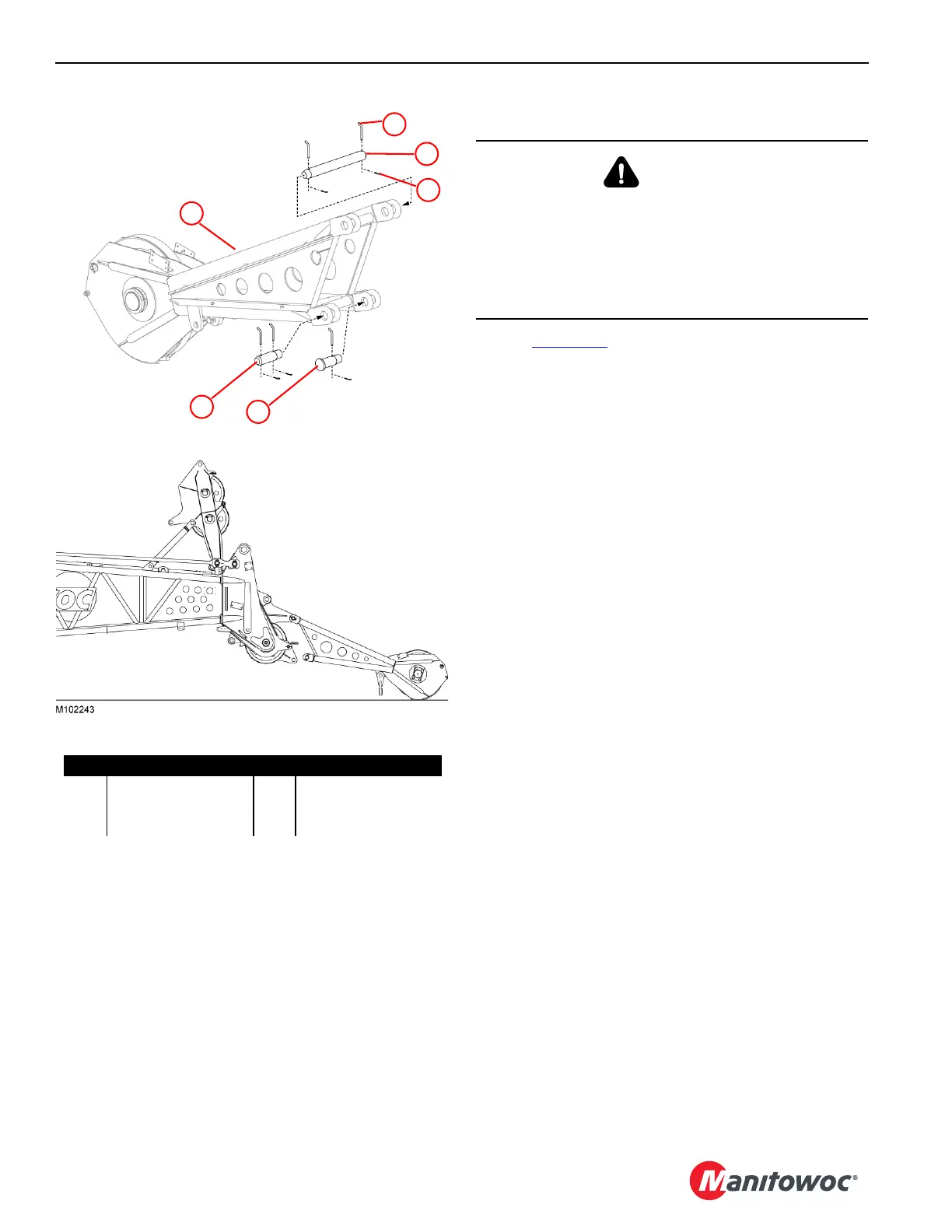
Install the Upper Boom Point
Refer to Figure 4-73 for the following procedure.
Pins for installing the upper boom point (1) are supplied with
the upper boom point and stored in their installation
locations.
1. Remove the upper pin (3) from the upper boom point.
The lower pins can remain in place.
2. Lift the upper boom point and move it into position at the
lower boom point.
3. Rest the upper boom point on the ground and align the
upper holes with the holes in the lower boom point.
4. Install the upper pin (3).
Secure the upper pin on both ends with the supplied
hitch pins (2).
Secure the hitch pins with the supplied cotter pins (4).
5. Install the lower pins (5 and 6) as follows when the boom
is raised:
a. Remove the lower pins from the upper boom point.
b. Slowly boom up to align the connecting holes.
c. Install the lower pins when the holes are aligned.
NOTE To avoid interference with the wire rope, one pin (6)
has a flat head. Install this pin in the correct
location and orientation (right side of crane, the
head facing inside), as shown.
d. Secure the pins with the supplied hitch pins.
e. Secure the hitch pins with the supplied cotter pins.
NOTE The upper boom point must be removed for jib
installation.
1
5
6
4
3
2
M100943
Figure 4-73
Item Description Item Description
1 Upper Boom Point 4 Cotter Pin (quantity 5)
2 Hitch Pin (quantity 5) 5 Pin, 2-hole
3 Pin 6 Pin, Flathead, 1-hole
Upper boom point ready
for boom raising.
WARNING
Crane Tipping Hazard!
To raise some boom and jib lengths, the upper boom point
shall be removed. The crane will tip if this is not done.
Refer to the appropriate Liftcrane Boom or Jib Capacity
Chart to determine the upper boom point requirements
and deducts.
 Loading...


