Manitowoc Published 08-06-19, Control # 237-09 2-27
MLC165-1 OPERATOR MANUAL SAFETY INFORMATION
Capacity Charts for Barge Mounted Cranes
Manitowoc provides two types of Capacity Charts for a crane
mounted on a barge or other supporting structure under
static conditions.
1. A Capacity Chart based on tipping when the crane is
anchored only to prevent shifting.
2. A Capacity Chart based on structural competence when
the crane is securely fastened for use as a pedestal
mounted crane.
NOTE Unless otherwise specified in a machine list
Capacity Chart, a 0 degree machine list Capacity
Chart rating applies to machine list not to exceed
1/2 degree. All other machine list ratings – 1°, 2°,
and 3° – shall NOT be exceeded.
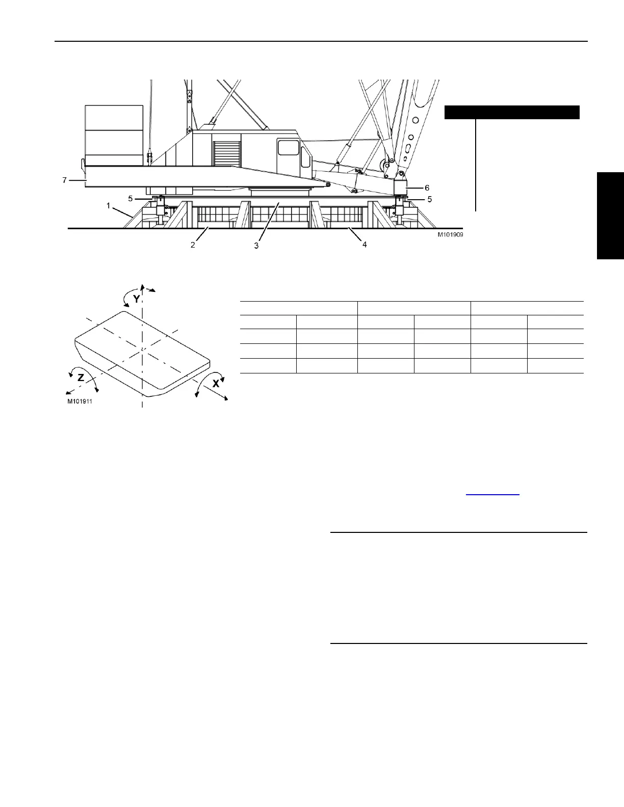
Shock Loading Caused by Barge Dynamics
Shock loads to the crane can be experienced when the
barge is subjected to up and down movement of wave action
(referred to as DYNAMICS). Figure 2-10
illustrates the
dynamic conditions of the barge which influence crane
capacity.
NOTE Manitowoc does not recommend crane operation
under dynamic conditions.
Figure 2-9. RINGER-Mounted-Crane
Item Description
1Bracing
2 Ring Support
3 Ring Assembly
4 Foundation
5Hook Roller
6 Boom Carrier
7 Counterweight Carrier
Figure 2-10. Barge Dynamics
AXIS TRANSITIONAL ROTATIONAL
SYMBOL NAME STATIC DYNAMIC STATIC DYNAMIC
X Longitudinal Surge Heel List Roll
Y Vertical Heave Yaw
Z Lateral Sway Trim Pitch
CAUTION
Structural Damage Hazard!
If the crane boom or structure is shock loaded during
operation, or there is any indication of shock loading, all
structural components of the crane shall be inspected to
detect cracks and other damage. Nondestructive test
equipment, such as magnetic particle or ultrasonic
procedures, is recommended for this inspection.