SETUP AND INSTALLATION MLC165-1 OPERATOR MANUAL
4-102
Published 08-06-19, Control # 237-09_v2
Install the Wind Speed and Position Light
Components
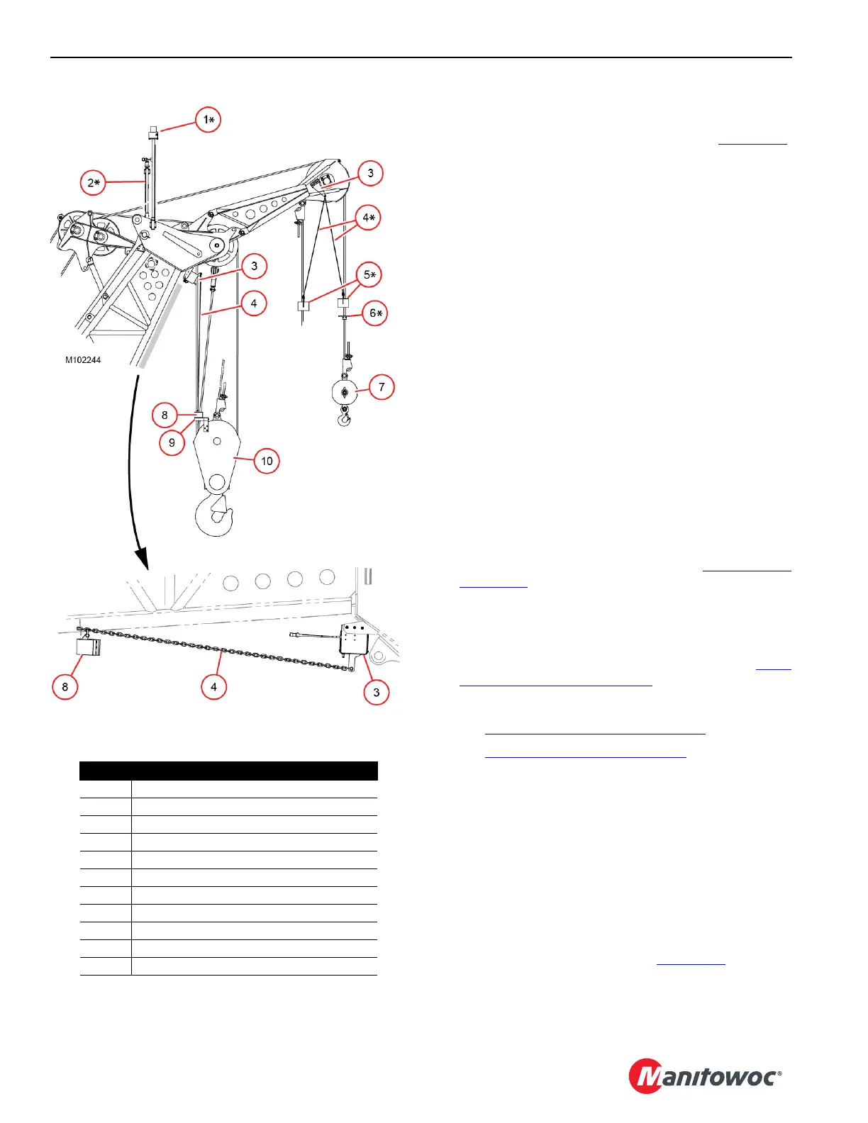
If any wind speed or position light components (Figure 4-75)
have been removed, re-install them now.
Refer to the following drawings at the end of this section:
• Electric Accessory Assembly, Position Indicator Light
• Electric Accessory Assembly, Wind Speed Sensor
NOTE To provide good ground for the wind speed
indicator bracket, use star washers to attach the
bracket to the boom or jib top.
Connect Boom Wiring
Refer to the ESI Boom Wiring drawing at the end of this
section.
1. Connect electric cables in the boom and jib to the proper
receptacles.
2. Connect CAN terminators to unused plugs. Failing to
perform this step will cause a fault alert and the
corresponding function will not operate properly.
3. To prevent dirt and moisture from entering electric
components, connect dust caps to all unused plugs,
CAN terminators, and receptacles.
Install the Boom Load Lines
1. Route the load lines up the boom. See Figure 4-99 on
page 4-127.
2. Pull the load lines approximately 20 ft (6,1 m) past the
end of the boom.
3. Install the load block(s) and hook-and-weight ball after
the boom is raised to a convenient height. See Boom
Raising Procedure on page 4-51.
4. Read the following topics:
• Wire Rope Installation on page 4-117
• Load Line Reeving on page 4-126.
• The Wire Rope Specifications chart located in the
Capacity Chart Manual supplied with the crane for:
- Parts of the line required for various loads
- Wire rope lengths and notes about the hoisting
distance for various parts of the line
- Maximum spooling capacity of the load drums
• Reeving diagrams at the end of this section
Install the Boom Block-Up Limit Components
Install the block-up limit components (Figure 4-75) according
to the ESI Boom Wiring drawing at the end of this section.
Figure 4-75
Item Description
1 Position Indicator Light
2 Wind Speed Indicator
3 Limit Switch (lower and upper boom point)
4 Chain
5 Weight with 2-Chain Attachments
6Lift Plate
7 Hook-and-Weight Ball
8 Weight with 1-Chain Attachment
9Lift Block
10 Load Block
* Stored in Parts Box
STORED
 Loading...


