Manitowoc Published 08-06-19, Control # 237-09_v2 4-95
MLC165-1 OPERATOR MANUAL SETUP AND INSTALLATION
Install Boom Top
See Figure 4-68 for the following procedure.
NOTE Determine if the lower boom point sheave clusters
require removal or modification. See Remove or
Install Lower Boom Point Sheave Clusters on
page 4-99 for instructions.
1. Using the assist crane, remove the boom top from the
trailer:
a. Using a basket hitch, attach four synthetic lifting
slings (3, View B) to the top chords of the boom top
(1) at the location shown.
b. Connect the synthetic lifting slings to the hooks of
the assist crane.
c. Adjust the position of the slings so the boom top is
approximately 9 in (229 mm) out of level when lifted
(butt end lower than top end).
d. Lift the boom top off the trailer.
2. Lift the boom top into position at the last insert (4, View
C) and align the top connector holes.
3. Remove the four connector pins (5, View D) from the
storage brackets.
4. Install the top connector pins (5, View D), lower the
boom top and install the bottom connector pins. The pin
heads must face the outside.
5. Secure the pins with cotter pins or safety pins.
6. Block under the lower boom point sheaves.
7. Disconnect and remove the lifting slings.
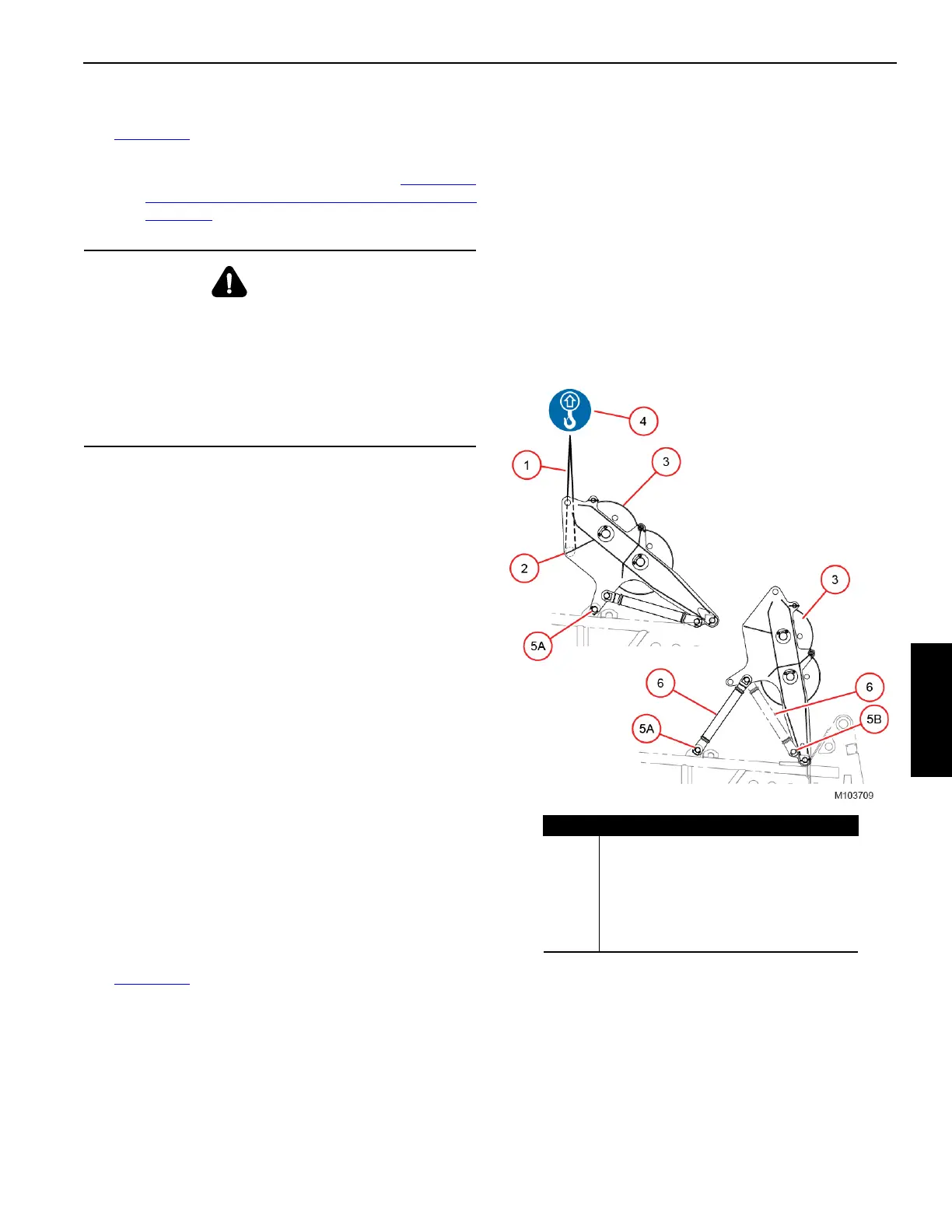
Raise Wire Rope Guide
See Figure 4-69 for the following procedure.
1. Using a basket hitch, attach the synthetic lifting sling (1)
to the cross brace (2) in the wire rope guide (3, View A).
2. Attach the lifting sling to the hook (4) of the assist crane.
3. Hoist just enough so the pins (5A, View A) are loose and
remove the pins (5A).
4. Slowly hoist to rotate the wire rope guide to the working
position (View B).
5. Remove pins (5B, View A) and rotate the struts (6) from
the stored position to the working position.
6. Install pins (5A, View B) to connect the struts (6) to the
lugs on the boom top.
7. Store pins (5B, View B) in the lugs on the wire rope
guide.
8. Disconnect the lifting sling.
WARNING
Crane Tipping Hazard!
To raise some boom and jib lengths, the two outer lower
boom point sheave clusters shall be removed. The crane
will tip if this is not done.
Refer to the appropriate Liftcrane Boom or Jib Capacity
Chart to determine the lower boom point sheave
requirements and deducts.
View A
View B
Figure 4-69
Item Description
1 Synthetic Lifting Sling — 6 ft (1,8 m) Long
2 Cross Brace
3 Wire Rope Guide
4 Assist Crane Hook
5 Pin with Cotter Pins (4)
6Strut
Approximate mast angle = 126°
 Loading...


