Manitowoc Published 08-06-19, Control # 237-09_v1 3-33
MLC165-1 OPERATOR MANUAL OPERATING CONTROLS AND PROCEDURES
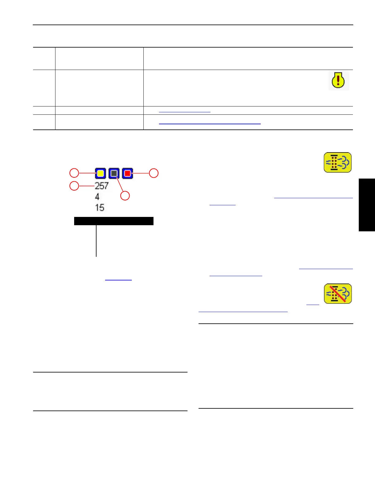
ENGINE WARNING LIGHTS AND FAULT
CODES
The warning lights shown in Figure 3-3 will come on when an
engine fault exists. This applies to both Tier 3 and Tier 4
engines. Service the engine as follows:
• Amber warning light (1) ON. Service the engine at the
first available opportunity.
• Red stop light (2) ON. Service the engine as soon as it
can be safely done.
NOTE: The center indicator (4) has no function.
The engine manufacturer’s fault code (3) appears under the
lights. See the Engine Wiring Diagram supplied with the
crane for a description of these fault codes.
TIER 4 ENGINE FAULTS
SCR Regeneration
Displays one of three conditions:
• When on, indicates that the after-treatment
system requires an SCR regeneration within the next
few hours. Use the SCR switch to manually start an SCR
regeneration cycle (see SCR Regeneration Switch on
page 3-15).
• When flashing, indicates that the SCR is in regeneration
mode. The operator may sense a reduction in power. No
immediate action is required.
• When flashing and the red stop light is on, indicates that
regeneration is required but is inhibited. The operator
will notice a significant reduction in engine power. Turn
off the regeneration inhibit switch and perform a manual
regeneration immediately (see SCR Regeneration
Switch on page 3-15)
SCR Regeneration Inhibited
When on, indicates that SCR regeneration has
been inhibited by the SCR switch (see SCR
Regeneration Switch on page 3-15).
7 System Faults Data Box
Displays activated operating limits and faults. See the MLC165-1 Main Display
Operation Manual for a complete list of fault symbols and for instructions on
scrolling through the faults.
8
Tier 4 Engine Fault Alert
Symbol
Appears in the upper right corner of the information screen, in the
upper left corner of the Tier 4 engine data box, and an alarm turns on
to alert the operator. See the MLC165-1 Main Display Operation
Manual for a complete list of Tier 4 engine faults. Take corrective
action when this alert is activated.
9 Tier 4 Engine Data Box See Tier 4 Engine Faults
.
10
Tier 4 Engine Warning Lights
and Fault Codes
See Engine Warning Lights and Fault Codes
.
Table 3-12. Main Display Information Screen
CAUTION
Avoid Engine Damage!
Immediately correct the underlying cause of any engine
fault.
Item Description
1 Amber Warning Light
2 Red Stop Light
3 Fault Code
4 Has No Function
2
1
3
4
Figure 3-3. Engine Warning Lights and Fault Codes
CAUTION
Aftertreatment System Damage
Do not place the SCR regeneration switch in the inhibit
mode unless directed to do so by a Manitowoc or
Cummins technical advisor.
If SCR regeneration is inhibited for an extended period,
the SCR will become damaged and require replacement.
Using the regeneration inhibit mode may result in loss of
engine power or shutdown by the ECM and the need to
service or replace the SCR.